
XenonZcar.com - Z31 Air Fuel Meter Calibraition
I am going to assume here that you know where the AFM (air flow meter), ECCS (engine computer) and the TPS (Throttle Position Sensor) are located. If you don't, Download your Factory Service Manual or get a Chilton book and study it so you know where to find them. *WARNING* - Do this modification at your own risk as a last remaining option to getting your car running correctly. Usually the Z31 does not need any changes to the meter for operation.
- Metric socket set, extensions, and a ratchet.
- #2 Phillips screwdriver
- Small drill bit
- Drill
Tools Needed
- Drive the car for a while until it is fully warmed up - at least 5 miles. You want the engine completely up to operating temperature before starting.
- Park car and put chocks behind wheels so it will not roll anywhere in neutral. You are going to spend a little time with it running while doing the adjustments, and you don't want it to start moving while doing this
- On the passenger side, remove the top kick panel and side kick panel. 4 Philips screws.
- Unhook courtesy lamp from top kick panel. Set panels and screws aside.
- Locate and remove 1-10mm bolt that secures ECCS unit to the vehicle.
- Pull ECCS out of its compartment, and set it out on the floorboards, leaving wiring harnesses connected to it. Remove plastic cover from the top of the ECCS.
- On top of the ECCS, locate an adjustable knob recessed inside.
- Using a small regular screwdriver, gently turn the knob COUNTERCLOCKWISE until it stops. Don't force it any further. It will break if you use too much force.
- Start the vehicle. Assuming that it is still at full operating temperature, run the engine up to 2000 RPM's, and hold it at that speed for 2 minutes.
- After the 2 minutes is up, continue to hold the RPM's at 2000. Look at the side of the ECCS unit. Through a small hole in the side cover, you should be able to see 2 led's. One is green, the other one red. While holding the RPMs at 2000, observe the led's. Verify that the GREEN led blinks on and off more than 5 times in 10 seconds. Don't worry about the red one yet.
- If the green led blinks more than 5 times, it tells you that the oxygen sensor is working. If it doesn't, the service manual directs you to some different troubleshooting steps involving the oxygen sensor.
- Assuming your green led is blinking as it should, release the gas pedal and let the car idle.
- Get under the hood, and disconnect the wiring harness from the TPS (throttle position sensor).
- Race the engine up to about 4000 RPMs under no load three times, and then let car sit and idle.
- Observe the led's in the ECCS unit. What should happen here is that the green and red led's should blink simultaneously at about a 2-3 second interval. Give it a half a minute or so to stabilize, then make the determination as to whether or not they are blinking in unison, as they should. If they do, stop here and put your car back together. No adjustment is necessary.
- If they are not blinking simultaneously, shut the car off, and begin removal of the airflow meter.
- First, remove the 4 -10mm bolts securing the air filter cover in place.
- Next, use a #2 philips screwdriver to loosen the clamp that secures the air duct to the front of the AFM.
- Gently pull the ductwork off of the front of the AFM.
- Using the #2 philips screwdriver, loosen the clamp securing ductwork to the rear of the AFM.
- Using the sockets and a ratchet with an extension, remove the bolts securing the AFM to the vehicle. (Note: the AFM is actually bolted on the bottom with 4 bolts to a piece of sheet metal. There are screws you need to remove that secure the piece of sheet metal to the vehicle frame.)
- Remove the wiring harness connected to the AFM.
- Gently pull the AFM from the ductwork and remove it from the engine compartment.
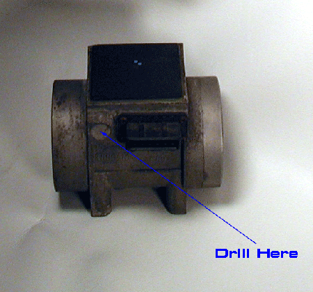
- Take the AFM to the workbench, and set it on its side, with the connector for the wiring harness facing upwards.
- Locate a round metal circle (approx. 1/2 inch in size) to the left of the harness connector. You are going to have to drill some holes in this plug, so it can be pried out.
- USE CAUTION HERE! Use the pin vise with a small drill bit to carefully drill a hole in the center of the plug. You must be VERY CAREFUL as there is very little room (5.5mm) for error. If you drill too deep, you can damage the variable resistor that is just underneath this plug. This is why I used a hand-powered drill, instead of a power drill. A power drill can get away from you quickly, and if you let the drill bit go too far down, you will damage the AFM. It is a Costly part - $500.00 to replace from Nissan.
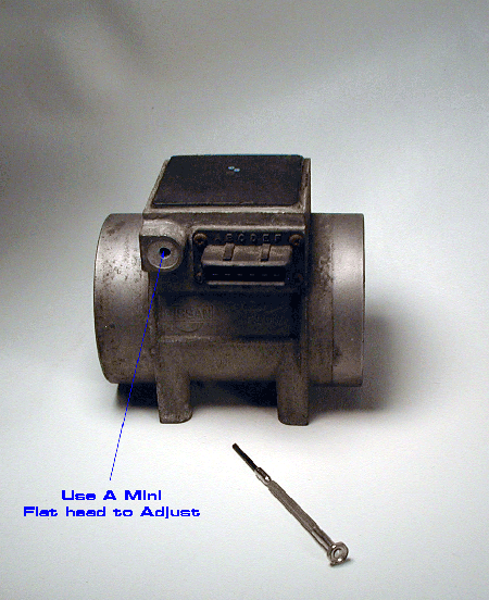
- After drilling the holes, I had a slot big enough to insert a small regular screwdriver into and pry out the plug. I had to work with it a little bit, as this plug is a very tight fit. Be careful prying it out.
- After the plug is gone, you will see a variable resistor inside that is adjusted with a regular screwdriver. This is what we will adjust to correct the idle mixture. Blow out the hole with compressed air to remove any stray metal shavings.
- Reinstall the AFM, reconnect the air ductwork, and reinstall air filter cover. Reconnect TPS harness and AFM harness. Tighten everything to spec, as you don't want any air leaks in the intake.
- Start the car, and drive it around for a while to get the engine completely warmed up again.
- Park the car, put wheel chocks back in place, and once again, run the engine up to 2000 RPM's and hold it there for two minutes. Then race engine up to about 4000 RPM's three times under no load, then release throttle and let the car idle.
- Disconnect TPS harness once again.
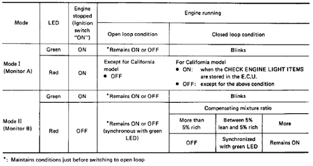
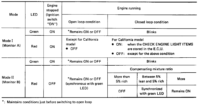
- Observe the led's in the ECCS. Mine had a blinking green with a solid red at this point. Follow the Below Chart to Set.
- Experimentation with it, turning ½ turn at a time counterclockwise, got the mixture so lean the engine RPM dropped noticeably. The only thing that happened was that the led's both came on and stayed on, with an occasional blink at about 30 second intervals.
- I then moved the variable resistor back to the starting point; I had kept close track of how much I had turned the resistor.
- I then turned it in ½ turn increments clockwise, keeping an eye on the led's. After about three full turns, the red led finally began to blink. It was not blinking in unison with the green one, so I kept moving the resistor clockwise. I turned it in ¼ turn increments at this point, until the led's blinked in unison, at approximately 2-3 second intervals.
- At this point, I decided the required results had been met. I then reconnected the TPS harness and took a drive. Everything seemed to be OK, the car was running fine, so I made a plug out of a piece of hardwood to replace the metal one that was removed. Then I rechecked all the clamps, bolts, etc. to be sure everything was tight and in place properly.
- Reinstall the ECCS unit, reinstall the kick panels, and then you are done.
Procedure
Hope this helps clear up some of the mystery of adjusting the AFM when it becomes necessary.