
Z31 Fuel Sending Unit Modification and Repair
Overview
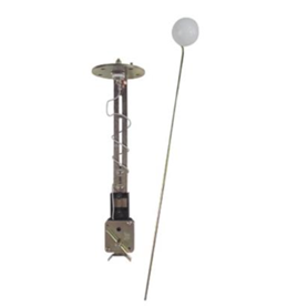
The OEM fuel sender works via a cylinder float design that rides on a rail with a copper line for contact. It provides two readings, one for the main gauge and one for the sub gauge. The rail provides a resistance range that differs based on the Meter type.
For Analog systems on the main gauge, your range will be approximately 6Ohms Full, approximately 80Ohms Empty, and ½ tank approximately 30-35Ohms.
For Digital systems on the main gauge, your range will be approximately 10-20ohms Full, approximately 480-520ohms Empty, and ½ tank approximately 100-110Ohms.
While compact in design, they suffer from corrosion and as a result the contacts on the float cannot make good contact on the slider of the sender which causes incorrect readings on the gauge. You can try cleaning the contacts and may find success. Another issue is the thin copper contacts on the float degrading to the point they break off, causing the entire module to become inoperable.
Originally, revised editions of the senders were created that used a float design that solved most of these issues. Digital versions either don’t exist or are NLA. The Analog versions can still be found but are quickly increasing in price and scarcity.
The Fix
What does exist is a wide range of Universal Fuel Senders designed for fuel cells. These work in the same fashion as our OEM floats, and as a result can be modified to work with our tanks and gauges. They vastly range in Ohm Ranges. Sadly, they won’t exactly match our ranges but we can definitely get close enough.
The types of senders we are looking for will need a Terminal post for the signal and ground themselves to the fuel tank plate via contact. The sender I used was a Tanks Inc. TNK-TAN-GML, which provides a 0-90 Ohm range and is adjustable in terms of height.
Using this sender, our harness, and the fuel tank plate; We can assemble a simple sender that will operate our main gauge in a close enough range.
Items Needed
- A Universal Fuel Level Sending Unit that matches your Meter
- Your Stock Fuel sending Unit
- Drill Bits and Drill
- Spade connectors
- Multimeter
- Sandpaper
- Wire strippers and crimpers
- Tape measure
Procedure
I've done this using the mentioned Universal Fuel Level unit and on a Analog 85 where my oem sender no longer worked. The process should generally be the same for other models.
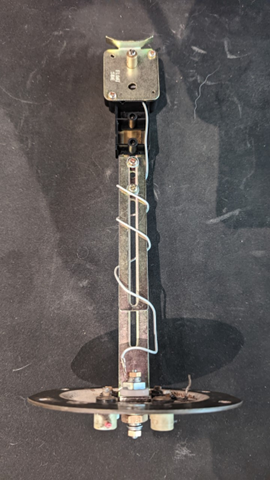
Start by disassembling your stock fuel sending Unit. You will only need the plate where the wires are connected and the harness attached. Cut the individual wires attached to the plate and save both for later.
Now disassemble the Universal fuel sending Unit, basically you just want to get rid of the plate it comes with. If you're using the Tanks Inc unit, you simply need to take the nuts off the middle terminal post and the play will come off (Save all hardware). There will be a gasket that sits in the plate, you will need that seals the entire setup.
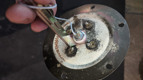
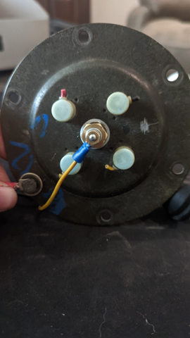
Now take your stock fuel sending plate and drill a hole in the center just large enough that the gasket from the universal unit can sit in. Make sure to sand the area around the hole on the bottom of the plate to provide good contact between the plate and the unit. You will also want to sand down to metal one of the plates screw holes, this will act as our grounding point for the harness. Test fit your unit and plate together, It will look like this.
Now you need to take a depth measurement from where the plate rests on top of the fuel tank and the very bottom of your tank. Mine was a bit dented on the bottom while also being resealed, but I measured 10inches. The universal fuel sending unit is around 8inches in length (not including the float being attached) so I had to cut the unit down to about 5inches in order to clear the float over the baffle.
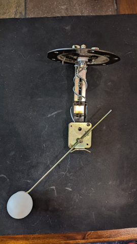
Now assemble the modified sending unit to the stock plate by sliding the terminal through your drilled hole, make sure you place the gaskets in the order they came. Tighten everything down.
Use your multimeter to check for continuity on metal parts of the unit and the sanded area of the screw hole. If it's showing continuity then you're good to go. Also check there's no continuity between the sanded area of the screw and the signal terminal on the unit.
Now slide on the float into the unit, you will need to slide the float in from the opposite direction to get the correct reading. Make sure the total length from the bottom of the plate to the bottom of the float is the total length you measured earlier, for example my unit is a total of 10inches from bottom of the plate to bottom of the float. You will also need to make sure the float maxes the unit out to the top of the plate and bottoms out at the total length. Play around with the float position, once you have a good placement, cut any excess arm off. For more accurate reading, try to place the halfway point of the float where half of your depth measurement is (IE. ½ tank)
With your harness, you will want to find which wire is the main signal wire and the ground wire using the FSM (Section EL). For my harness, this was the yellow wire (Main Signal) and the black wire (Ground). Strip back the signal wire and attach a spade connector and do the same for the ground. Attach the signal wire to the post, you will attach the ground wire to the bolt that goes in the area you sanded. You can perform a continuity test between the metal on the unit and the ground side of the harness.
Now that everything is put together, take your creation to the car and plug in the harness. Clip the ground to the plate and make sure it's making contact. Turn the car into the on position. You should now be able to move the float and change the gauge accordingly. If the float is all the way up (Full), but your gauge shows empty, you need to flip the float around as it is reversed. Play around with the float position and check for accuracy, you may need to adjust the float arm length or the unit height to narrow it down.
Once you've got everything setup, put the unit into the tank. Point the float facing the driver side, as there's the fuel pump baffle to the passenger side that will block the float from going to empty, make sure you also clear over the sender's baffle. You should now have a somewhat accurate gauge. If you want to make it even more accurate, there are ohm converters you can use to narrow the readings correctly.
Sources used on this page:
-
Written by: Brandon Ferrell