
1987 - 1989 Z31 Instrument Cluster Upgrade (Lighting and Needles)
The reason I did this to my Instrument cluster was to update it a bit, give myself a more visible red needles at night and more brightness.
I started this project was because my Instrument cluster was dim and with LED's being the craze and my job being based on LED's (Fiber Optic Lasers) I figured oh, Why not.
Items Needed
- 3 - Mini SMT LED bulbs for the #158 - (Amber)
- 1 - 2722 T1.5 - (Amber)
- 6 - T1.5/Neo Wedge/12mm Base bulbs - (Red)
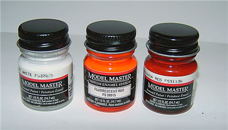
- Testors Model Master Paint Flat White - FS37875
- Testors Model Master Paint Fluorescent Red - FS28915
- Testors Model Master Paint Insignia Red - FS31136
- Phillips screwdriver
- Flat Head Screwdriver
- Ratchet
- Assorted sockets
Here is a Chart for the bulbs:
The Process
- Start off by taking the lower steering column plastic trim off. Use a Phillips screwdriver on the screws. There are 3 screws.
- Next take off the trim around the steering wheel (plastic casing just behind the wheel); There are 4 screws, 2 per side. I just take the top portion out.
- Now the Switch pods at each side of the Instrument cluster must be removed - See: Switchpod bulb replacement
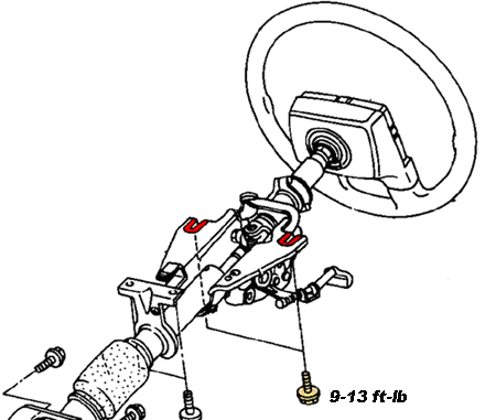
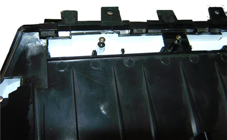
- Once the Switch pods have been removed the next step is to drop the steering column. Under the steering column find the 2 Bolts that hold it up to the frame (these are usually golden looking in color because of its rust proof coating). Loosen them up enough but just before the bolt comes out. This step ensures you can get the Instrument cluster out without taking off the steering wheel.
- If you have followed this so far you now are close to getting your Instrument Cluster out.
First, there are 2 Phillips head screws found on the Instrument cluster Bezel. Remove those.
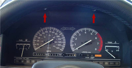
- Carefully remove the Bezel out of the Instrument cluster area.
- Once the Bezel is removed you should be able to see the 2 Phillips screws on the left and the right of the Cluster. Once you remove those 2 final screws the Cluster should be free.
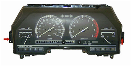
- Slowly pull it forward and position it where you can get your hand behind it.
- Each connector has a Tab on top and bottom; both have to be pressed in order to remove the connector from the Cluster.
- At this point the Instrument Cluster should be easy to sneak between the steering wheel and the dash.
- Now, we are trying to upgrade the lighting here to LED bulbs. We will need to make a few modifications to the Instrument cluster.
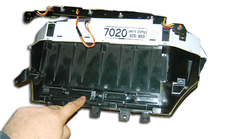
- Start by taking out the Gauge Face Lighting bar found on top of the Instrument Cluster. There are a total of 3 small Phillips head screws on the main lighting bar and 2 auxiliary bulbs for the temp and fuel gauges.
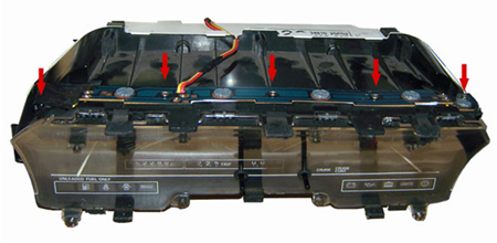
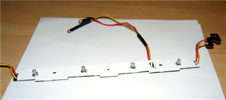
- Carefully pull off the 3 PCB’s (Lighting Bar and Auxiliary bulbs). The image shows the set up used for the lighting of the needles and Temperature/Fuel Gauges.
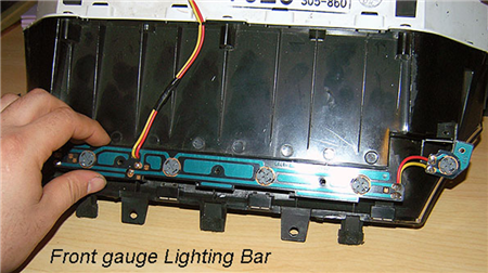
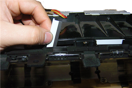
- Front Gauge Lighting Bar has been pulled away. Now you should be able to see the Lighting Diffusers. These small white opaque lexan pieces diffuse the light to give you a smooth glow of light on the needles.
- Now here are those diffusers, you should keep these if you want to use incandescent bulbs or led’s. If you are using UV lighting you can remove them as the low wavelength of UV light is barely visible if under 400nm. To get good UV light you must get LED’s that have a wavelength between 365-390nm. Most over the counter LED’s are not true UV light and their wavelength is more into the visible light spectrum or 405nm.
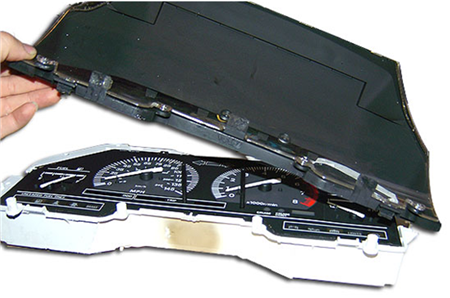
- Next we will take the Acrylic plastic cover off, be careful as it is acrylic and it is more brittle then lexan / Plexiglas. There are 4 Phillips screws found on the front and 5 Phillips screws from the back. After all the screws are out you can carefully undo the 4 tabs on the rear and the 2 tabs on the front that hold the 2 pieces together.
- After all tabs have been carefully separated, lift up on the cover.
- In order to have good luminance with a directional LED you must reflect it somehow. The bad thing about a Light Emitting Diode is that the light output is directional or focused where as an incandescent bulb gives light in a 360º manner.
- Since I used red LED Neo Wedge bulbs for the Front Illumination of the needles something must be done since the red LED is closer to the infrared part of the spectrum and the light emission is focused even though the LED has a flat end on it.
- I went to my local hobby store that carries Testors model paints. Mix the white paint very well as the premium Model Master Testors is an oil based enamel paint.
- Now, carefully apply an even coat of Flat White to the underside of the Front Illumination Light bar (the underside is flat black from the factory). This Flat White paint will allow the LED’s light output to reflect of the trough it sits in and on to the gauges. Also do this to the (2) PCB’s where the Temp and Fuel Level bulbs mount to.
- Apply white paint on the inside of the trough where the bulbs rest in place. Make sure to always stir your paint to keep the pigments from settling at the bottom. It will take several coats of white.
Without the white paint the needles will not get much lighting from a red LED.
- Let me take a few moments of your busy time here and show you more pictures of the Instrument Cluster and the bulbs going in.
- This instrument cluster has an acrylic plastic light diffuser, very neat for 20 year old technology; even some cars today don’t have a diffuser but just bulbs.
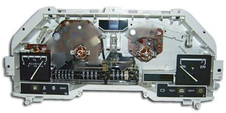
- Our Gauge Face plate is a full instrument cluster lexan piece. As you can see there are 2 squares missing, these are the Temperature and Fuel level gauges.
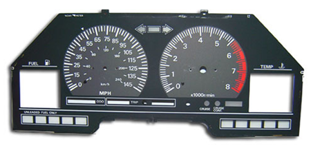
- The Face plate is an actual orange thin sheet of Lexan screen printed with flat black and flat white. On the back are various dabs of white flat white paint. This is done to evenly distribute the light source on the numbers and lines.
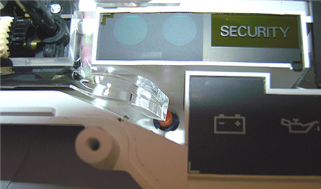
- This is the factory bulb for the lower Odometer/Trip illumination. It is a 2722 bulb that can be replaced with a #74 Bulb. Notice the Acrylic diffuser.
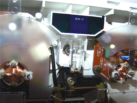
- Again in the middle bulb you can see the Acrylic diffuser. This is done to evenly disperse the light. This bulb can be replaced with a #194 bulb.
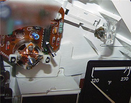
- This is the bulb just behind the Temperature gauge and it lights up the right side of the instrument cluster. This bulb can be replaced with a #194 bulb.
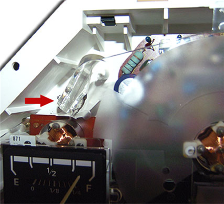
- This is the bulb just behind the Fuel Level gauge and it lights up the left side of the instrument cluster. This bulb can be replaced with a #194 bulb
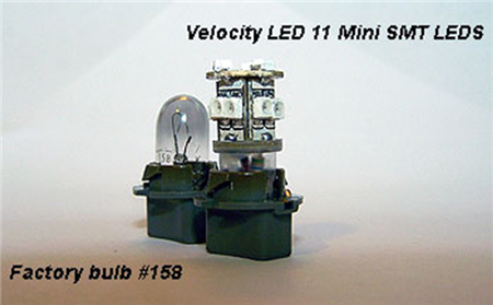
- This is a side by side comparison of the 11 Mini SMT LED bulbs from Velocity LED's and the factory #158 bulb. These are the tallest bulbs you can fit in the stock location.
- The Needles on the Z31 are just a poly with a weight on the thicker end, they are not like the newer cars that use a clear lexan needle with a strip painted on the bottom and lighting underneath. What I did to my needles to make them just a bit different is that I painted them a Fluorescent Red.
- The Fluorescent Red is more like an Orange/Red; this paint will glow under true black light. I didn’t quite like the thought having bright orange needles so what I did is I went back to the hobby store and bought their Model Masters Insignia Red, which is a flat paint. I also have a paint mix tray. I experimented under the black light until I got a mix where I still had glow from the Fluorescent paint but yet it darkened some.
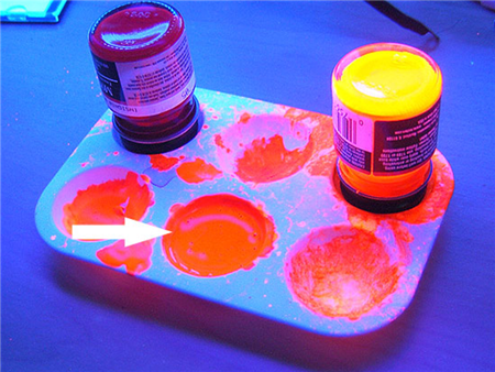
- Here is a shot of the paint mixed to my liking; it looks more red then orange. The paint now matches the tachometer in color.
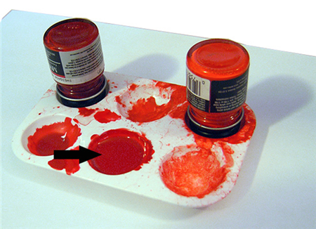
- This method is great for those of you who want to use Stock bulbs, LED’s or even black light bulbs as the needles will look red during the day, will look red with regular bulbs at night and when used with UV black lights they will glow!
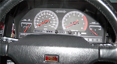
- Here you can see the needles now in red. They do glow under a black light too for those who are going with the black light front lighting.
- This picture shows what the red needles look like if used with Black light.
- Install the needles, Clean up the Acrylic cover and install that. Button up the screws.
- Go out to the car and make sure the gauges work. If everything is ok you can go ahead and finish tightening the rest of the screws.
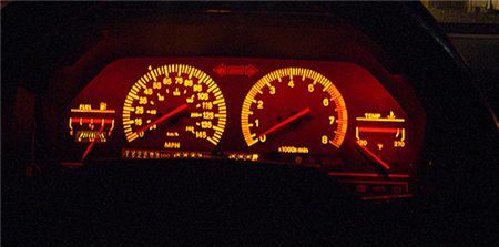
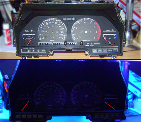
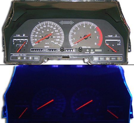
- Below you can see what it looks like with light and with UV light. (There is no backlighting yet at this point).
- My main point is to have red needles here and as you can see, mission accomplished.
- Slide the cluster in and plug in the illumination connector which is the one behind the tachometer. Turn the parking lights on and make sure the LED bulbs are in the right way. They will not work since they have a + side and a – side. Yup don’t reverse the polarity if not they will not turn on.
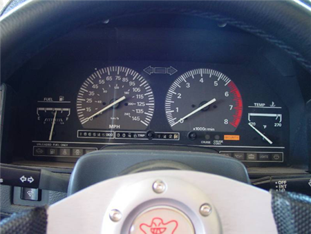
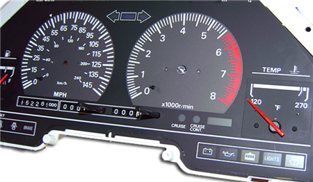
- The pictures show the stock white needles, the red colored needles and the final instrument cluster.
- Take notice on key points here. All needles glow red, the Temperature and fuel level gauges also have a cool red effect.
- I can also do UV light if I wish and the needles would glow fluorescent red!
- This adds cooler running LED to the Instrument cluster, They last much longer then an Incandescent bulb, and with the mix I used, I am able to light up the Fuel and Temp gauges red.
Sources used on this page:
- Writeup by: Nivo88T