Z31 Nistune ECU Tuning

Question, What is Nistune?

NIStune RealTime boards provide a way to make your factory Engine Control Unit (ECU) fully reprogramable similar to aftermarket Engine Control units for a fraction of the price. They use the latest technologies available on the market today to keep the size of the board small and cost lower.

Having your factory ECU reprogrammable means that either yourself or a knowledgeable tuner can quickly and easily retune your factory ECU with minimal installation and setup. They are tuned using the NIStune software.

Unlike any other type of daughterboards available for Nissan vehicles on the market, NIStune boards are the only real-time tuning solution available on a single small standalone board.

Once initially programmed, the NIStune board is permanently installed in the owners ECU (engine control unit). The ECU can then be tuned on a dyno via either the USB connector for Type 1 boards

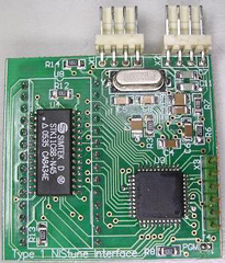
The Z31 will use the type 1 board from Nistune shown below


Installing the NISTUNE board

I installed my own NISTUNE board into my ecu myself and it wasn't that hard to do with basic soldering knowledge.


First start by removing the 4 screws on both the front and back cover of the ECU being careful as they can strip the heads if the ECU was exposed to the elements.

Once you pull your covers off you will need to determine the type of ECU you have as there were 4 board revisions through out the Z31 life. They are as follows:


Click on the ECU to view image

Prepping the Board for Installation


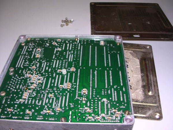
Next you will need to clean everything that you will be soldering/un-soldering with acetone as the factory covers everything in a lacquer to protect it from the elements.


Removing the ROM Chips

Now you can start the work of removing the EPROM chips that hold the Fuel and timing maps. To do this you will need to heat each pin of the PROM chip and wick away or use a De-soldering iron or Sucker to remove the hot liquid solder. The process is the same for each ECU but the location and number of EPROM chips will vary by model. The PDF Instructions linked below will explain this process in detail

  • 1984-1985 Models
  • 1986 Model
  • 1987 Model
  • 1988-1989 Model

Installation of the Socket

Now that the ROM chip(s) are removed you can install the socket for the NISTUNE board. Align the number 1 pin with the number 1 pin on the board and press into the holes left from de-soldering the ROM chip.

  • 1984-1985 Models
  • 1987 Model

Installing the CPU Connector to the ECU board

At this time you need to add the connector for the CPU connection. This attaches 2 different ways depending on model year. For 84-87 models you need to solder the wires directly to the CPU Pins in the correct locations. On 88-89 models there is a open set of solder pads on the board to make the connection. Below I will go over both connection types.

1984-1987 Models

the Image below shows the CPU chip that is mounted on the board of the ECU, This will be a 40 pin chip marked with "HD6802W" on the top. We are only worried about the Following Pins:


  • 24 - Connects to Wire 2 Grey Next to Purple
  • 25 - Connects to Wire 3 Grey Next to Black
  • 34 - Connects to Wire 1 Purple
  • 37 - Connects to Wire 4 Black

1988-1989 Models

On the 1988-1989 models Nissan added solder pads on the ECU board they are located near where the ROM chip was located. The Connections are in the same order as the wires.


  • Connector Wire 1 Purple - ECU throughhole #33
  • Connector Wire 2 Grey Next to purple - ECU throughhole #32
  • Connector Wire 3 Grey Next to black - ECU throughhole #31
  • Connector Wire 4 Black - ECU throughhole #30

Installing the USB Connector

Now you need to figure out where you want to mount the USB connector. Most people remove the ECU diagnostic Mode selector and modify the hole to fit the connector.

The Reason is The existing bracket from the ECU diagnostic Mode selector fits the USB connector, but requires the hole to be drilled and filed out to fit the connector plug through. The diagnostics can be retrieved from Nistune software, so this is no longer required. The diagnostics selector will be replaced by the USB socket.

To do this, Remove the 2 screws from the diagnostic Mode selector and place in a safe place. Now Unscrew the potentiometer from the bracket, and either cut or desolder the wires to the potentiometer from the ECU and ensure that if the wires are cut, that the exposed ends are adequately insulated. You can Use Tape or Loop the Wires and shrink wrap them.


Now carefully drill out the hole where the selector switch was located making sure you do not hit any components inside the ECU. Once the hole is opened up you will want to file the sides smooth to allow for the squared USB plug to fit into the hole.


Then put the USB-B socket inside the bracket and refasten the bracket as seen below.


Installing the NISTUNE Board

Now you can fit the NISTUNE board into the newly installed socket and connect the CPU cable to connector X1 and the USB cable to connector X2.

You also want to ensure the PGM jumper is not soldered if the board was previously programmed. Also watch the Knock sensor cable if Equipped.

The last thing before reassembling the ECU is to secure the NISTUNE board and connections. You can use Hot Glue to do this by coating the area with a generous amount.


Testing

Now you can reconnect the ECU to the Factory wiring and connect the USB cable to your laptop with the NISTUNE software installed.

Next Turn the vehicle Ignition switch to ‘ON’ without starting the car, Your fuel pump should operate as normal and the car should be able to start. If not then immediately turn off the engine and attempt to diagnose the problem following the Nistune diagnostics document.

If your ECU pulses the fuel pump, injectors, fuel regulator, flashes LEDs randomly (or they just stay on) or does not start then your ECU could be reading a corrupt ROM image. Testing has shown that a corrupt ECU can keep the heater element on longer than 1 second and blow it like a fuse. Ensure a corrupted image in your ECU is rectified immediately and is powered off if corruption is suspected to avoid this situation possibly occurring to you.

Following Nistune USB device installation, configuration and connection, pressing the ‘USB Consult’ button should highlight in red, and viewing the ‘Consult Display’ should show the battery, temperature and AFM voltages. Turn the vehicle Ignition switch to ‘START’ briefly to run the engine. Whilst the engine is running the ‘Consult Display’ should indicate more parameters and map tracing should be available in the various graphic windows available from the Nistune software.

Refer to the Nistune Software Operators Manual and Type 1 Quick Start Manual for more information regarding the installation of USB drivers and usage of the Nistune software. Refer to the Nistune Diagnostics Manual if you have problems connecting to the Nistune board.


Rom Sets and what to start with

The list below will tell you what ROM set to use as a base when tuning your Z

Nissan ECU number
BIN to start with
Nistune Board Model
23710-87EXX
J30_VG30E
Type 1
23710-98EXX
J30_VG30E
Type 1
23710-01PXX
Z31_EARLY_VG30
Type 1
23710-06PXX
Z31_EARLY_VG30 or Z31_LATE_VG30
Type 1
23710-10PXX
Z31_EARLY_VG30
Type 1
23710-02PXX
Z31_EARLY_VG30
Type 1
23710-25PXX
Z31_LATE_VG30
Type 1
23710-545XX
Z31_LATE_VG30
Type 1
23710-21PXX
Z31_LATE_VG30
Type 1
23710-26PXX
Z31_LATE_VG30
Type 1
23710-18PXX
Z31_MID_VG30
Type 1

Bin File Database

The links below will allow you to download Non OEM Bin files and also allow you to upload your own tune to share with Others.

Nistune Dealers and Tuners

Here you will find a list of Nistune Dealers, Installers, and Tuners. If you wish to be added to this list please contact us at admin@xenonzcar.com

Shop Name

Location

Services Offered

Z31online

Littleton, Colorado

Authorized Nistune Dealer and Installer

JE Import Performance

6600 Moravia Park Drive, Suite A,
Baltimore, MD 21237

2WD and 4WD Dyno Tuner


Sources used on this page: