


S130 Automatic To Manual Climate Control Swap
⚠️ Warning:
This may seem like a simple and straightforward procedure, however, there is always the possibility of error, and you are responsible for any damage you cause by attempting this procedure yourself.
Introduction
This guide provides the necessary steps to modify a 1979–1983 Datsun/Nissan 280ZX climate control system from Automatic Climate Control (ACC) to Manual Climate Control (MCC).
Throughout this procedure, the systems will be referred to as auto control and manual control. Most components from the auto control system can be reused for manual control, except for the following:
- Control unit attached to the front of the heater unit
- Water cock valve attached to the heater unit
- Heater hoses plus two fittings located in the engine compartment
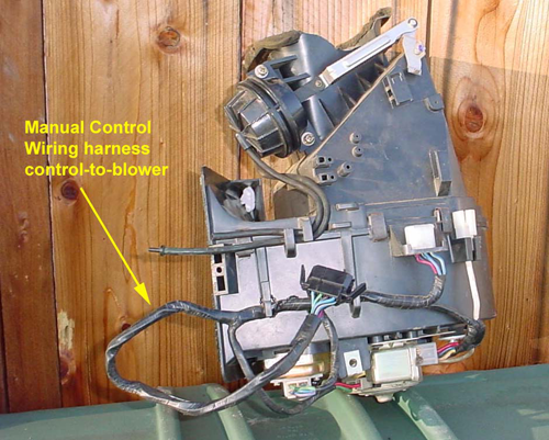
- Wiring harness leading from the control unit to the blower
This modification requires removing the heater unit from behind the dash. To access it, the dash and the supporting bar in front of the heater unit must be removed.
If all necessary parts are on hand, the complete removal, modification, and reinstallation can be completed in approximately one weekend.
This procedure is written as a detailed step-by-step guide for those unfamiliar with dash removal or heater/AC system work. If you have prior experience, feel free to skip to the relevant sections.
Dashboard Removal
2.1. Tools and Supplies Needed
Tools:
- Two or three sizes of Phillips screwdrivers
- Standard screwdrivers (for possible hose clamps)
- 22 mm metric socket (for steering wheel nut)
- 10 mm socket
- 10 mm open-end or box-end wrench
- 12 mm socket
- Ratchet set with various length extensions
- Sharp knife or razor blade
Supplies:
- Heater hose (5/8” ID × 7/8” OD)
- Vacuum hose (3/32” ID × 7/32” OD)
- Silicone spray lubricant
- Foam insulation strip (1/2” width × 3/8” thick)
- Antifreeze
2.2. Preparation
- Drain coolant from the radiator. With the engine on and heater set to heat mode, run the engine briefly to drain coolant from the heater core.
- Disconnect the negative battery cable.
- Label all wire connectors and leads as they are disconnected.
- Store and label each unit’s mounting screws in separate envelopes.
2.3. Steering Wheel Removal
- Remove the horn pad from the center of the steering wheel by pulling it off. Do not remove the horn actuation mechanism underneath.
- Remove the steering wheel nut using a 22 mm socket.
- Pull the wheel off the shaft. If tight, bump one side of the wheel while pulling up, rocking it side-to-side. A steering wheel puller may be needed. Note: Align punch marks on the shaft and wheel hub during reinstallation.
2.4. Dash Removal
- After removing the steering wheel, remove the steering column shell cover (8 screws from below). Separate the two halves.
- Remove the combination switch (turn signals/lights & wipers/washer) by loosening the screw on the lower right rear and sliding it off the shaft. Note: Align the square pin and hole when reinstalling.
- Remove radio panel lower covers (under dash left & right). Disconnect wires from entrance lights and vacuum hoses from the vacuum control knob (MCC cars only).
- Remove instrument panel bracket covers on both sides of the radio panel to reveal bolts.
- Remove radio and panel, disconnecting antenna lead and wiring.
- Remove the instrument center ventilator (surrounds heater/AC control panel and center vents).
- Remove two heater control unit securing screws from the support beam.
- Disconnect the speedometer cable at the intermediate connector.
- Remove dashboard upper plugs (base of windshield) to access 4 screws, then remove them.
- Remove four lower securing bolts for the dash assembly.
- Disconnect instrument panel wiring connectors, labeling as needed.
- Pull the dashboard out horizontally while lifting the heater control slightly to clear it. Tip: Two people make this step easier.
With the dash removed, the heater unit, AC evaporator, and blower are now visible.
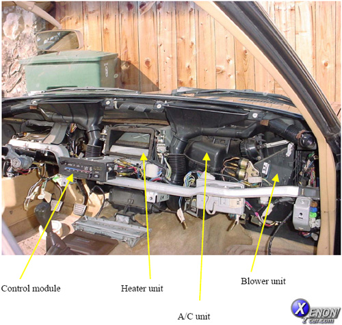
Figure 2-1 — Dash area after removal
Parts Needed for Modifications
Below is a list of components needed to convert from Automatic Climate Control (ACC) to Manual Climate Control (MCC). Many ACC parts can be reused, but the following must be replaced or sourced for manual control:
-
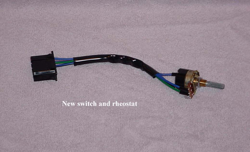
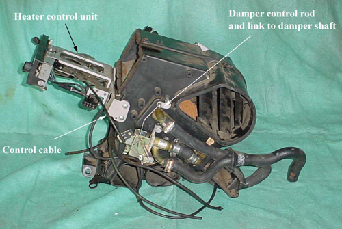
Heater/AC control unit — Contains the vacuum control switch, blower speed control, A/C micro switch, light, and water cock control cable.
- Consider replacing: switch/rheostat (recommended)
- Consider replacing: lamp (recommended)
- Test micro switch for actuation
Tip: Check the lamp with a 12V source — it’s nearly impossible to replace once installed without removing the dash again.
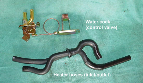
- Heater water cock — Controls water inlet valve and connects mechanically to air mix door.
- Air mix door interlock rod, set screw, and attachment to air mix door shaft.
- Heater hose inlet and outlet pair — Unique to manual control.
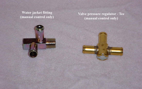
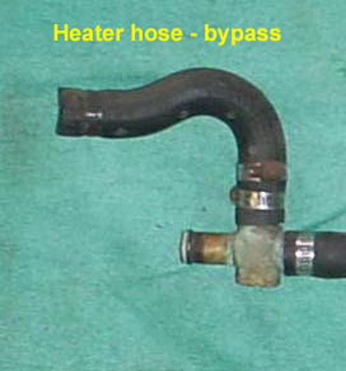
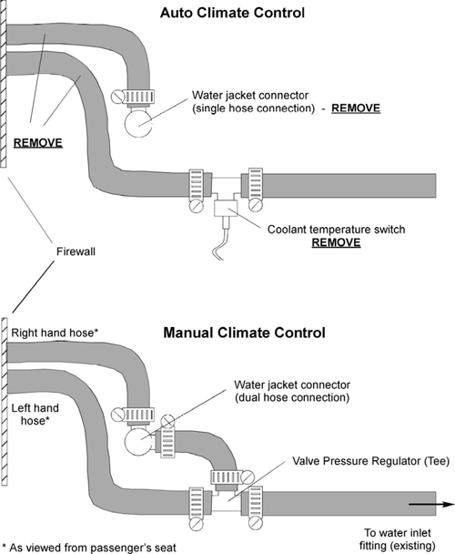
- Heater hose bypass piece — Runs from water jacket connector to valve-pressure regulator tee.
- Water jacket connector — Manual version has two hose connectors instead of one.
- Heater hose valve-pressure regulator tee — Replaces temperature switch in auto unit.
- Blower wiring harness — From control unit to blower.
- Vent bypass switch — Manual only (mounted on lower left dash panel).
- Blower (fan) control amplifier.
| Part Description | Part Number |
|---|---|
| Heater Control Unit | ** 27030-P7101 |
| Blower Switch* | * 27041-P7100 |
| Water Cock | 27116-P7100 |
| Interlock Rod, Set Screw, and Bracket | 27119-P7100 |
| Water Jacket Connector | 27195-P7100 |
| Valve-Pressure Regulator (Tee) | 27188-Q0105 |
| Blower Wiring Harness | 27038-P7101 |
| Heater Hose Pair (Inlet/Outlet) | 27180-P8100 |
| Heater Hose Bypass | 27183-P8100 |
| Control Unit Light/Lamp* | * 27134-P7100 |
| Vent Bypass Switch | 27037-P7100 |
| Blower (Fan) Amplifier | 27177-P7100 |
* Recommended replacements. ** The control unit can be ordered new from Nissan or sourced from a salvage yard. Rebuild as a minimum by replacing the switch/rheostat and lamp to avoid future dash removal.
Parts to be Removed From Automatic Climate Control
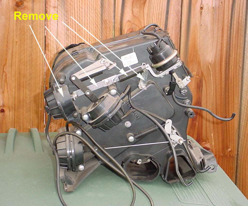
Refer to Figures 4-1 through 4-4 for visual guidance on which components can be removed or retained when converting from Automatic Climate Control to Manual.
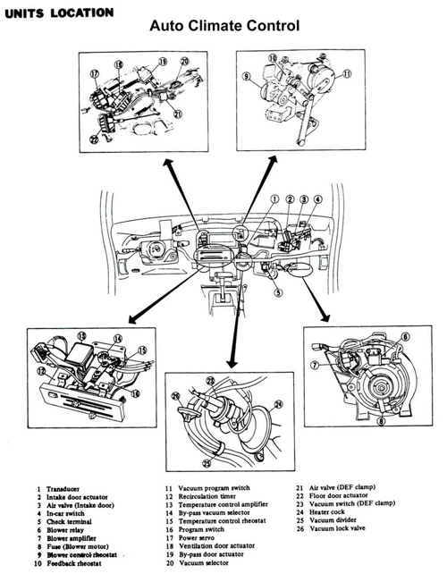
From Figure 4-1
| Part No. | Description | Action / Notes |
|---|---|---|
| 1 | Transducer | Remove — see Fig. 4-3 for detail |
| 2 | Intake door actuator | Do not remove — part of blower assembly |
| 3 | Air valve — intake door | Do not remove — replace vacuum hoses |
| 4 | In-car switch | Remove |
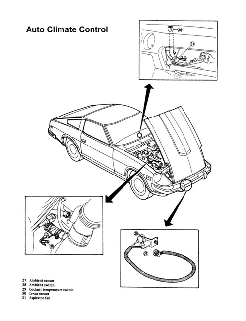
From Figure 4-2
| Part No. | Description | Action / Notes |
|---|---|---|
| 27 | Ambient sensor | Remove or leave — unimportant |
| 28 | Ambient switch | Remove or leave — unimportant |
| 29 | Coolant temperature switch | Remove — see Section 6 for hose configuration |
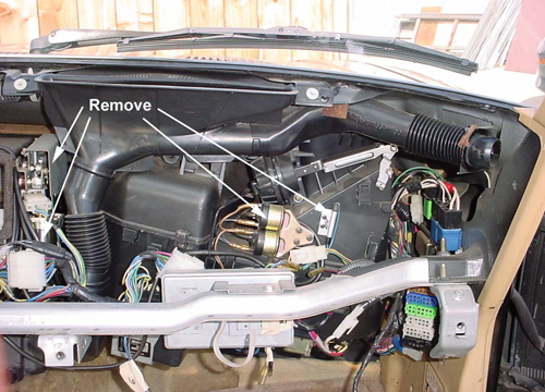
Heater Removal and Modifications
The heater unit requires the most modifications in this conversion. All automatic control hardware must be removed, the air-mix door mechanism must be modified, and the heater water cock replaced. Ventilation doors or dampers must also have their vacuum lines rerouted.
Tip:
Removing the dash support bar makes heater unit removal much easier. This bar sits directly in front of the heater, A/C evaporator, and blower.
- Unbolt the dash support bar from both ends and the steering column from the bar. Leave one bolt on the right end to control the drop.
- Drop the bar from the right, lift the left, and remove from the car, noting removal sequence.
- Unbolt and remove defrost ducts beneath the windshield, labeling left/right.
- Drain coolant system. Loosen heater hose clamps between the heater unit and A/C evaporator. Tip: Cut hoses just outside the firewall for easier removal.
- Disconnect the two vacuum hoses from the firewall and two from the inlet damper at the blower top. Save all old plastic connectors, especially “T” connectors.
- Unbolt heater unit: two bolts at the firewall, two at the transmission tunnel.
- Disconnect and label wiring harnesses.
- Pull heater unit away from the firewall, feeding hoses through.
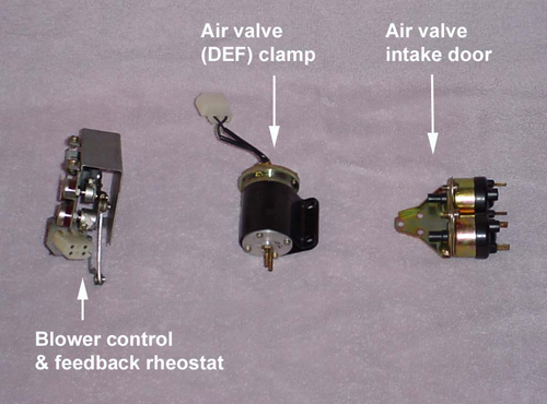
- Remove auto blower control unit from the right side (parts 9–11, Fig. 4-1).
- Remove the entire control unit from the heater front (parts 12–16, Fig. 4-1). Save vacuum hoses and fittings.
- Install the manual control unit (see Fig. 5.3-1 for placement).
5.2 Air-Mix Door Modifications
The auto control uses a vacuum power servo to move the air-mix door. This servo must be removed and replaced with a manual control rod on the right side.
Save all vacuum tubing and fittings. The servo is held by two screws, with one small screw securing the arm to the door shaft.
Next, remove the auto control water cock valve (right side of heater unit).
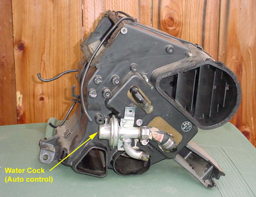
Note:
The short heater hose from the water cock to the heater core inlet must be replaced with new hose and connected to the manual control water cock.
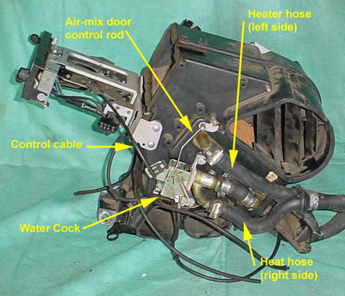
5.3 Water Cock Replacement
- Test and observe the new manual water cock operation. Mark closed position for cable adjustment.
- Install new manual water cock (Fig. 5.3-1).
- Install short heater hose with clamps.
- Route heat coil to back of heater unit (Fig. 3-1).
- Remove small cover plate on back of heater unit.
- Install heat coil into back, secure with two screws.
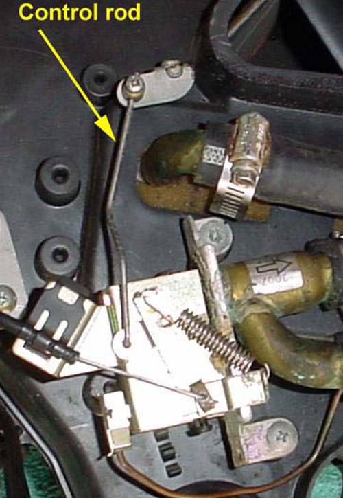
- Install control rod from water cock to air-mix door shaft (Fig. 5.3-2).
- Install control cable from control unit to water cock (Figs. 5.3-1, 5.3-2, 5.3-3).
- Adjust control rod/cable in Section 5.4.
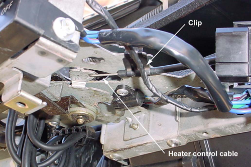
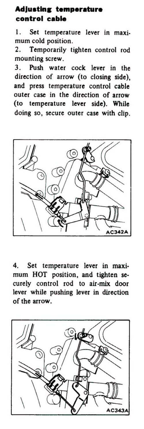
5.4 Water Cock Control Cable Adjustment
Adjust the control cable from the control unit to the water cock per the factory shop manual instructions included in this procedure.
Engine Bay Modifications
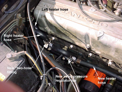
- Replace the heater hose connector at the back of the engine (above #6 spark plug). Tip: Remove the fuel injector blower (right side, spark plug side) for easier access. Removing spark plug wires (after numbering) and intake manifold vacuum lines may also help.
- Replace the auto control single-hose fitting with the manual control two-hose fitting.
- Remove the old fitting and install the new one using Teflon tape on the threads. Orient the fitting as shown in Figure 6-1.
- Replace the water temperature switch (auto system) with the valve-pressure regulator tee.
- Replace remaining heater hoses and connect as shown in Figures 6-1 and 6-2.
- Route new heater hoses through the firewall and connect per Figure 6-1.
Note:
From the passenger seat view — the right-hand heater hose goes to the two-hose fitting above the #6 spark plug, and the left-hand heater hose goes to the valve-pressure regulator tee.
- Leave the fuel injector coolant blower out until the engine has been restarted and checked for leaks.
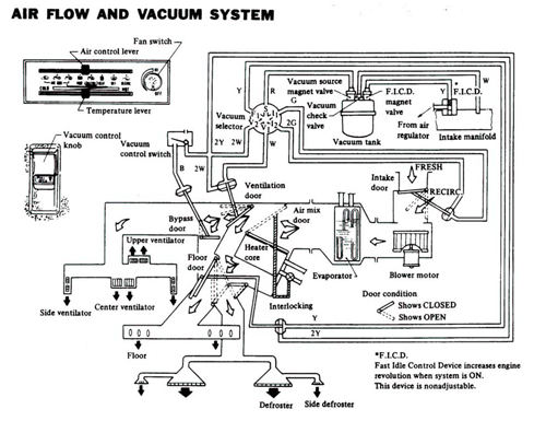
Blower Unit and Vacuum Tank Modifications, Vacuum Hose Routing
7.1 Blower Unit Modification
The Nissan parts fiche lists different part numbers for the blower amplifier between Auto and Manual control models. The Auto control amplifier must be replaced with the Manual control amplifier. The blower relay and fuse unit are identical, but the wiring harness must be swapped.
- Remove all Auto control parts as outlined in Section 4, including the wiring harness from the blower to the heater control unit. Keep the wires attached to the fuse holder, amplifier, relay, and blower unit — they will connect to the new manual harness.
- Replace the two vacuum lines to the air intake door servo (top of the blower unit).
7.2 Vacuum Tank Modification
- Locate the vacuum tank at the right front side of the engine (with two solenoid valves on its backside). Refer to the shop manual if needed.
- No modification to the tank is required. The Auto system uses two lines through the firewall; Manual uses only one. Seal off the unused line — it comes from the tank body itself. The second line (from the black-capped solenoid) supplies vacuum for the Manual control.
- Replace this remaining vacuum hose with new material, as old hoses become brittle and crack over time.
- Remove and plug the unused second vacuum line. You may leave it in place to avoid a firewall hole — just clamp or seal it to prevent leaks.
7.3 Vacuum Hose Routing
- You should now have only one new vacuum hose running from the vacuum tank to the dash area.
- Before installing the heater unit, replace all vacuum hoses running from the vacuum selector (bottom of the control unit) to:
- the various servos
- the vacuum control knob/switch mounted on the lower driver’s side dash panel
Reference:
Use the vacuum diagram (Figure 7.3-1) for exact hose connections.
Installation, Testing and Checkout
8.1 Installation
- Ensure the heater unit is modified with the new water cock and vacuum hoses routed to their respective servo valves.
- Apply new foam insulation strips (½” wide × ⅜” thick with adhesive backing) to:
- The sealing edge of the front heater vent
- The side facing the A/C evaporator
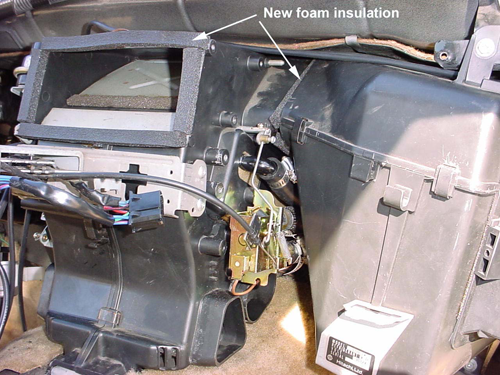
Figure 8-1 — New Foam Insulation Added - Position the heater against the firewall and secure with four bolts. Ensure proper mating with the A/C evaporator.
- Connect the vacuum hose from the vacuum tank to the vacuum selector (marked “S”).
- Lubricate heater hose fittings with silicone spray, slide hoses into place, and clamp securely.
- Attach the last two vacuum hoses from the intake valve (top of blower) to the heater control unit vacuum selector (positions I1 and I2).
- Connect the new wiring harness from the control unit to the blower.
8.2 Testing and Checkout
- Fill the radiator.
- Reconnect the battery negative terminal.
- Before reinstalling the dash and support bar, start the engine to test the heater, blower, and A/C.
- Run the engine until coolant warms up.
- Check for leaks at all new heater hose and fitting connections.
- Test all modes:
- Hot air at floor ducts
- Hot air at defrost ducts
- Cold air in A/C mode
- Blower speed adjustment via rheostat
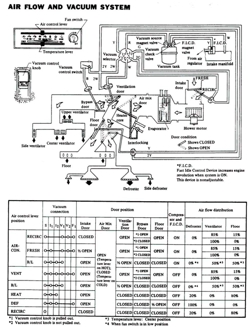
Figure 8-2 — Checkout and Testing 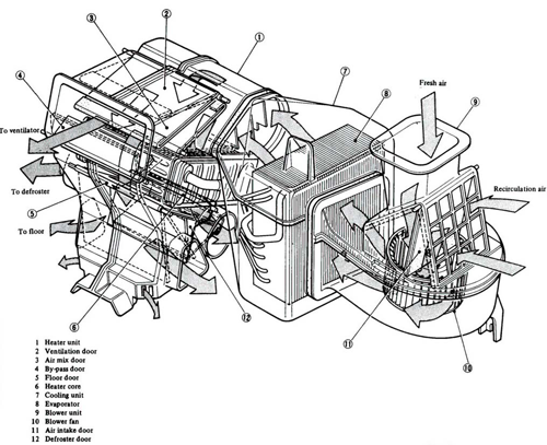
Figure 8-3 — Heater, A/C Unit and Blower
8.3 Completion
- Disconnect the negative battery lead before final reinstallation.
- Reinstall the fuel injector blower on the right side of the engine.
- Reinstall the dash support beam (reverse order of removal).
- Reinstall the dashboard (reverse order of removal).
- Reinstall the steering wheel and shaft covers.
Sources Used
- Written by: Roy Challberg
- 1979-1983 280ZX Nissan Factory Service Manuals