
USDM Wiring
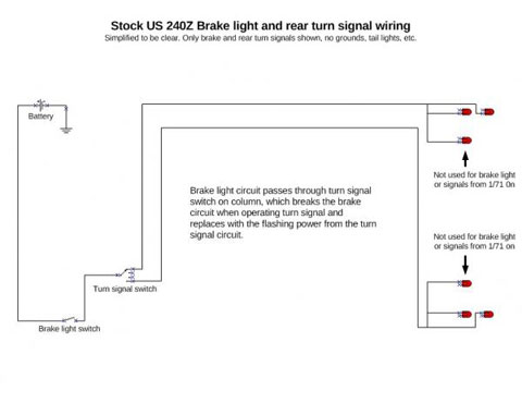
Here is a diagram of the stock US 240Z brake/rear turn wiring. This diagram is intentionally simplified to show only the most relevant details for this modification.


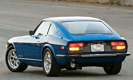
Here we will document the wiring changes needed to use JDM/Euro (amber bottom) tail lights in a US 240Z.
First lets define the US rear lighting, which is different than what Nissan used for the rest of the world.
*WARNING* - Do this diagnosis/mods at your own risk. We Are not responsable for any issues of your own doing.
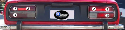
| # | Description |
|---|---|
| 1 | Brake and Turn Signal |
| 2 | Brake and Turn (Series 1) Tail Only from 1/71–end |
| 3 | Brake and Turn Signal |
And for comparison, most of the rest of the world got lights configured like this:
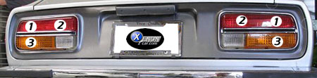
| # | Description |
|---|---|
| 1 | Brake and Tail Lights |
| 2 | Brake and Tail Lights |
| 3 | Turn Signal and Hazards |
The issue has always been that if you install the JDM lenses (amber bottom) with US wiring, you end up with both red and amber lights acting as both brake lights and flashers. Not optimal, to say the least. So what’s the fix? Get a bit creative with wiring.
Unlike most other mods I’ve done to my car—especially in the wiring—this one requires cutting and splicing
one or two wires (the exact number depends on your build date) in each tail light wiring harness.
This does not involve cutting the main harness—only the small harnesses with the bulbs in them.
I performed this on a spare pair of harnesses, but if you don’t have extras, you’ll need to modify the originals.
You have been warned.
Here is a diagram of the stock US 240Z brake/rear turn wiring. This diagram is intentionally simplified to show only the most relevant details for this modification.
Green/BlackGreen/Red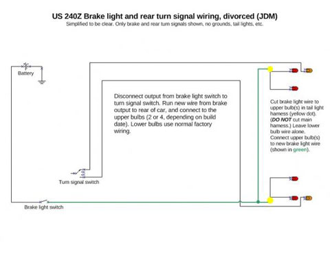
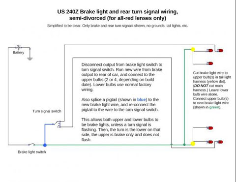
The Hybrid system combines the benefits of integrated and divorced brake/turn setups. One bulb per side acts as a dedicated brake light, while the other is integrated with the turn signal. This ensures maximum brake light visibility while turning.
The wiring is essentially the same as the JDM conversion, but with one addition: at the front of the new brake light wire, tap a pigtail into it and connect it to the wire from the turn signal switch that previously connected to the brake switch.