


Z31 Digital Dashboard Issues and Repairs

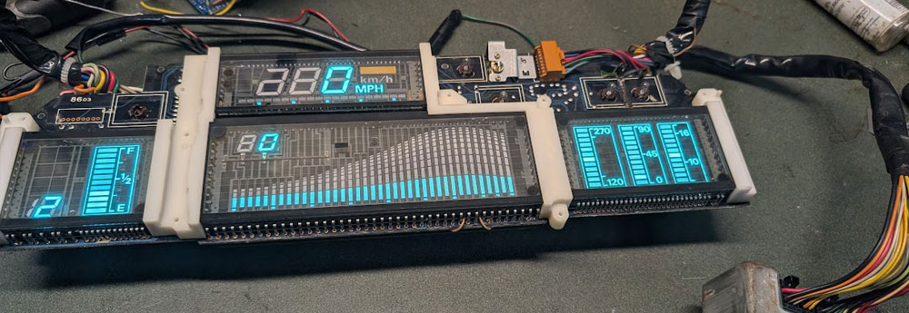
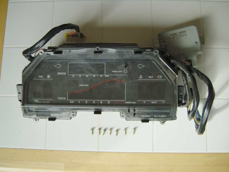
Early Z31 Digital Dash Cluster
The digital dash was part of an optional package that cost $1200 when new. This package also included an upgraded stereo and digital climate controls. These clusters are known for a fairly common habit of failing over time — either the display goes completely dark, or certain elements start disappearing.
Common Issues & Fixes
- Complete power failure: Often caused by bad capacitors or a failed power supply board.
- Missing segments: Usually due to cold solder joints, bad capacitors, or other failed internal cluster electronics.
- Flickering display: Can be traced to unstable voltage regulation inside the cluster.
Running Digital Dash Self-Diagnostics
The Z31 digital dash includes a built-in self-test mode to check for dead segments and other display issues. To run the self-diagnostics, follow these steps:
- Turn the ignition OFF.
- Press and hold both trip odometer buttons.
- While holding the buttons, turn the ignition to the ON position (do not start the car).
- Release the buttons once the diagnostics start.
- Watch the display carefully and check for any dead or missing segments.
Below are some Videos of each of the different Cluster types offered in the US Market cars. Canadian cars are very similar but the mesurements are in Metric. JDM Versions and AU Look the same as the Canadian model, But the wiring is completely different and I suspect any of the RHD cars are the same.
USDM 1984 Model Cluster Self Test
USDM 1985-1986 Model Cluster Self Test
USDM 1987-89 Model Cluster Self Test
Digital Dash Display Not Powering On
The most common cause of a Z31 digital dash failure is a faulty power supply unit (PSU) due to bad solder joints or poor contact. Below is the procedure to diagnose and repair this issue:
Steps to Remove and Inspect the Power Supply:
- The power supply unit is located above your right knee behind the trim panel that contains the hood release and steering wheel tilt lever.
- Remove the trim panel, then locate the PSU box (approx. 5"x5"x1"). It's held in place with one 10mm bolt and one 10mm nut. There are also two welded brackets secured with screws and two wire harnesses connected to the unit.
Common Fixes:
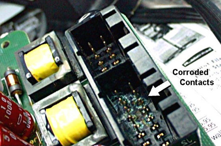
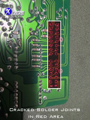
- Inspect the circuit board for cracked solder joints. A Nissan TSB recommended replacement (~$400), but re-soldering often fixes it.
- Check the connector pins; if they are loose, gently twist them with pliers to ensure better contact.
- For a permanent fix, you can solder the wires directly to the pins or wedge something between the connectors and box to keep a tight fit.
- Clean any corrosion from the contacts while you have the unit removed.
Need Your Power Supply Repaired?
This is a service we provide at XenonZcar. Pricing is about $100 plus shipping.
Contact Sales@xenonzcar.com
to have your Power Supply Unit professionally tested and repaired.
Alternatively, you can source a replacement digital cluster or swap to an analog cluster (note: this requires significant wiring modifications). Instructions can be found here
Digital Speedometer Always Reads "0"
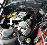
If your digital dash shows “0” at all times, the issue is usually a failed speed sensor or a broken speedometer cable. The speed sensor is sealed with epoxy, but over time the epoxy cracks, allowing water or salt to damage the internals.
Step 1: Test the Speedometer Cable
- Locate the speed sensor on the fender well near the battery. It has the speedometer cable and four wires (red, green, black, yellow).
- Unscrew the locking ring and remove the cable from the speed sensor. Watch for the black plastic alignment ring—do not lose it.
- Prop the cable so you can see the square end. Put the car in 5th gear and roll it forward/backward 3–4 feet.
- If the cable rotates about half a turn, the cable is good. If it doesn't move, the cable is broken.
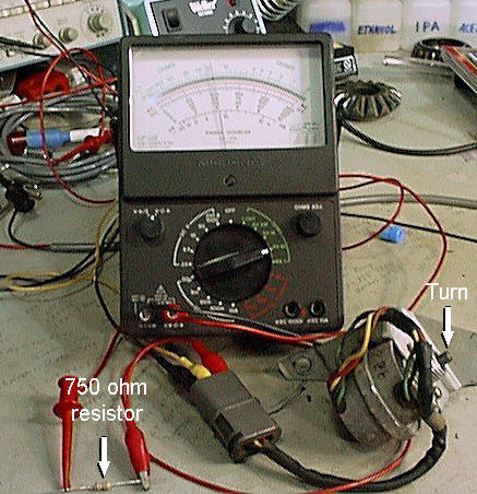
Step 2: Bench Test the Speed Sensor
You’ll need: insulated alligator clips, a multimeter (analog preferred), and a 5–6V DC source. Never apply 12V directly! If using the car battery, put a 750Ω resistor in series.
- Black: Ground
- Red: +12VDC
- Yellow: Signal
Connect power to the black (ground) and red (+DC) wires. Connect the multimeter to black and yellow, set to 10K–100KΩ. Slowly turn the sensor shaft:
- If working, the analog needle will swing or digital resistance will vary from ~200Ω to infinity.
- If you see no movement, the sensor is bad and must be replaced.
If All this Fails...
If these steps fail to correct your issue and the sensor and cable both test good, Then the issue is internal to the cluster. Usually the other gauges will still be lit up but the readings will not be correct at all. The Voltmeter will usually read 16 (Max) and the other gauges will read near 0.
A Lot of times this can be repaired here at XenonZcar as the issue is caused by one of the Ceramic IC boards internal to the Cluster. The solder cracks off and the ceramic surface and the only fix is to replace it with a updated version as solder will not stick back to the ceramic.
1984 Fuel and Coolant/Oil Pressure/Voltmeter Section Blank
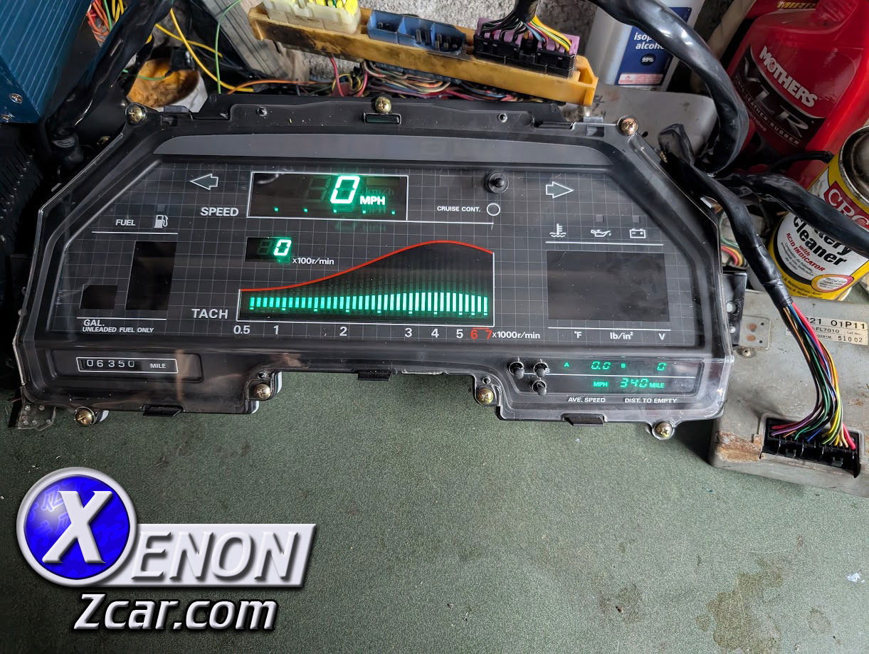
(Image: XenonZcar Garage)
On the 1984 Digital Clusters, a common failure is the Fuel Gauge section dimming over time and eventually going completely dark. This can also occur with the Coolant/Oil Pressure/Voltmeter section either individually or together with the fuel section.
The root cause is failed electrolytic capacitors on the cluster’s main board. When these capacitors fail, they leak electrolyte that corrodes the copper traces and surrounding components, leading to permanent damage if left untreated.
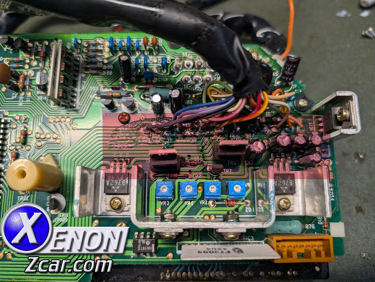
(Image: XenonZcar Garage)
In severe cases, the electrolyte seeps under transistors, Zener diodes, and even brightness control potentiometers. This can require extensive repair or complete replacement of the board.
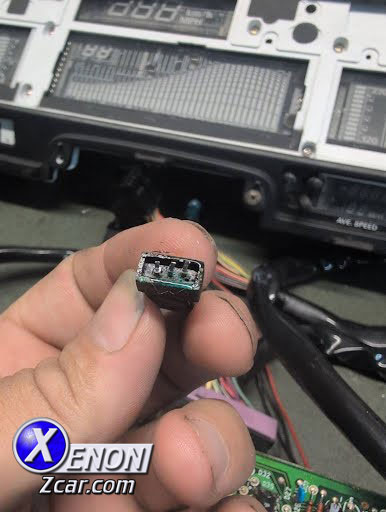
(Image: XenonZcar Garage)
If caught early, some damage can be cleaned and the failed components replaced. For minor board trace damage, bridging the broken traces can restore functionality. However, if corrosion spreads too far, the cluster may suffer complete failure.
Need Your Cluster Repaired?
This is a service we provide at XenonZcar. Pricing depends on the extent of damage.
Contact Sales@xenonzcar.com
to have your cluster professionally tested and repaired.
Cluster Removal
First, remove the combo switches on each side of the gauge cluster. While you are under the dashboard, it's recommended to also remove the two 10mm nuts holding the power supply unit to the dashboard and unplug the two connectors.- Remove the 4 screws holding the digital cluster bezel in place, then carefully pull out the bezel.
- Remove the two screws (one on each side) securing the cluster into the dashboard.
- Disconnect the three wiring harness plugs located across the top of the cluster.
-
For better access, remove the steering wheel:
- Remove the column covers by taking out the 4 Phillips screws. Unclip the covers from the column.
- Disconnect the key light and steering wheel control harness if equipped.
- Pull the horn pad off (start from the top). This will reveal the 19mm nut securing the wheel to the column.
- Loosen the nut but do not remove it completely. Wiggle the wheel side-to-side or use a steering wheel puller with the 8mm x 1.25 threaded holes.
- Once loose, remove the nut and pull the steering wheel off completely.
- With the steering wheel removed, you can now carefully pull the digital cluster out of the dashboard. I pull the bottom out first and then slide it towrds me being careful not to scratch the cluster lense.
Fuel Gauge Reads Inaccurately
One of the most frequent problems with the Z31 digital clusters is the fuel gauge reading incorrectly. Often, the gauge will read fine when the tank is full, but as fuel is used, the reading will suddenly drop to zero.
The primary cause is the design of the fuel sending unit. It uses a carbon trace to measure resistance based on the float’s position. Over years of use, the float fingers wear down the carbon, creating dead spots, or the fingers bend and lose contact. In some cases, the float fingers can even break off completely.
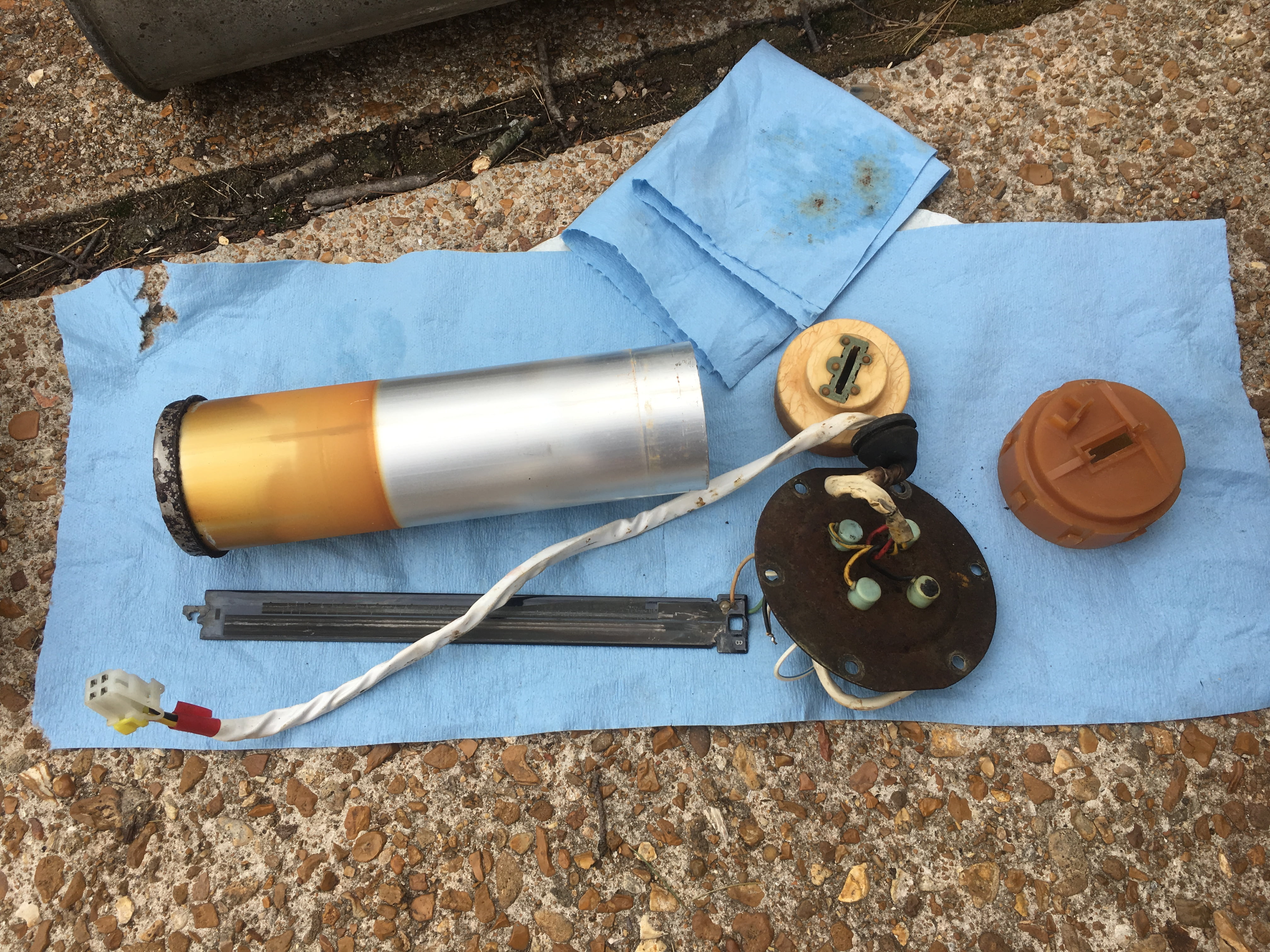
(Image: dafunkmonster of z31performance)
The sending unit is accessible from inside the hatch under the rear carpet and foam pad. A circular cover hides the wiring and access to both the sending unit and fuel pump.
⚠️ Important: Original digital dash fuel sending units are no longer available. Analog sending units use a different resistance scale, making them incompatible with digital clusters.
Some enthusiasts have attempted to design adapters to use the analog or aftermarket senders, but most solutions have not achieved 100% accurate readings.
One such product was from Cogworx. Their converter allowed a 10" 240-33 ohm fuel level sender (commonly used in marine applications) to interface with the digital dash. These were once available through The Z Garage , but are currently sold out.
Sources Used
- 1984-1989 Nissan 300ZX USDM Factory Service Manual
- EURO Market Nissan 300ZX Factory Service Manual
- Based on Write-up by: Frank Zemaitis, Added to By XenonZcar