


Nissan Versa Electric Power Steering Swap for Z31
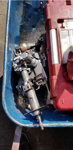
Want to clean up your engine bay without losing power steering? The 2007-2009 Nissan Versa EPS column is the answer. Grab the steering column (with control module) and intermediate shaft from a salvage yard.
Parts to Pull
- Versa steering column with attached EPS computer
- Intermediate shaft
- Wiring harness (cut close to the main harness)
Modification Process
Nissan Versa Electric Power Steering Swap for Z31
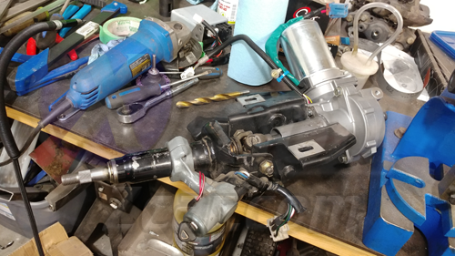
So, you're wanting to clean up the engine bay, but don't want to lose power steering? Well, the 2007-2009 Nissan Versa has the answer for you! Get out to the salvage yard and pick up the steering column (with attached computer), and intermediate shaft. You won't require many tools for this, but make sure to bring some wire cutters so you can grab the wiring harness that plugs into the control computer. Cut it as close to the main harness as you can to give yourself plenty of wiring later, and keep in mind the smaller connector is for the sub-harness that connects the torque sensor; don't cut this one.
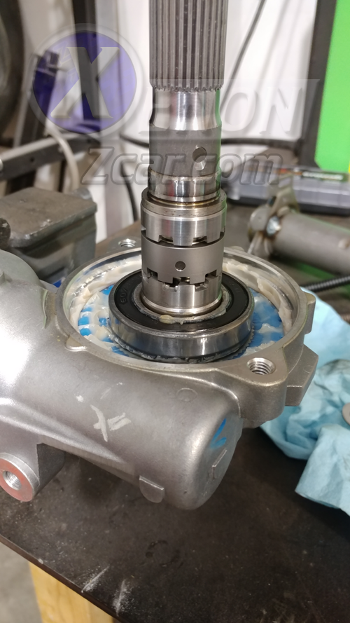
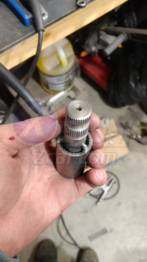
The torque sensor housing can be clocked in two orientations, I suggest rotating it 180 degrees from the stock position to provide yourself with a more compact unit. Make sure not to damage the components within, as these toothed gears are how the torque sensor does its thing.
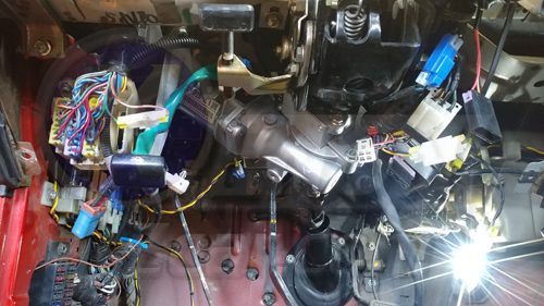
Removing the Stock Steering Column
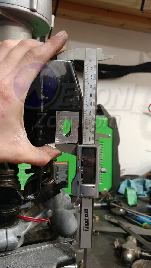
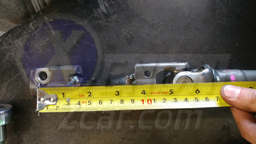
Remove the stock steering column. There are four 12mm bolts that hold up the column, and three Phillips/10mm bolts that hold the column tube/plate to the firewall. Disconnect the universal joint from the steering rack, and pull this assembly from the car. Disassemble the rear half of it, but keep all of the parts for now. I started by cutting down the main bracket, to 95mm.
Take the front piece of the stock intermediate shaft (that attaches to the universal joint behind the steering wheel) and cut it down to 76mm or so. You could cut it shorter, but I left mine this long when I was test fitting the components as it allowed plenty of room for adjustment.
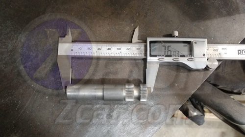
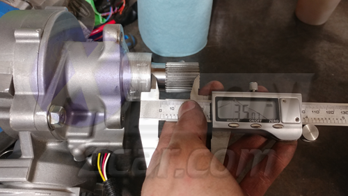
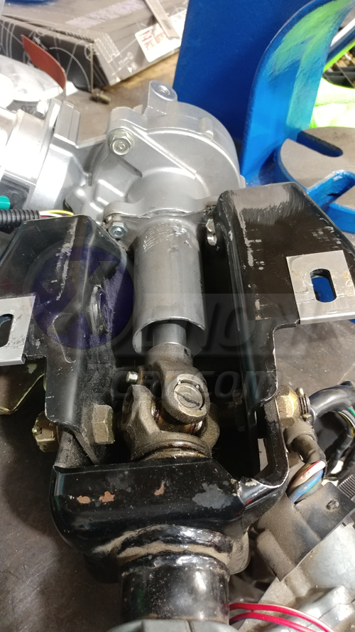
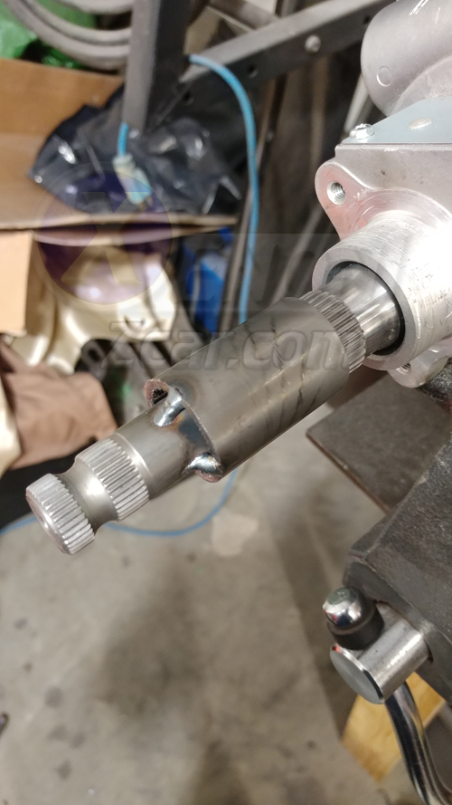
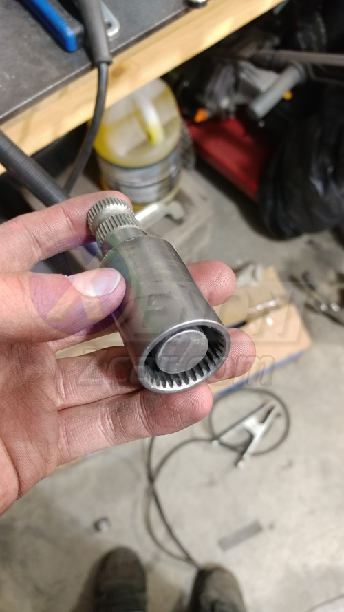
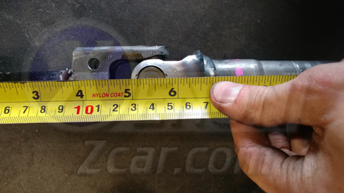
I cut the input shaft of the assist motor down to 35mm from the flange to the tip, you could leave it a bit longer but it's not really necessary. I recommend taping off the gap between the input shaft and the torque housing, as the needle bearing at the front is not shielded.
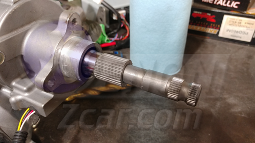
I cleaned up the input shaft on the motor, and the section of stock intermediate shaft, and as it turns out, the two fit together nearly perfectly. A complete fluke, but it made the process of fitting the motor up a lot easier when I was making adjustments, as well as keeping it in line with the front universal joint. I recommend leaving the stub long for now due to this.
Cut down the motor tube (attaches to the input side with three 10mm bolts) so it ends shortly before the universal joint. It doesn't pose much importance in our application, but the farther out we support it, the better.
Assembling & Fitting the Modified Steering Column
Loosely assemble the modified column and determine the angle you want the motor at. Check for clearance between the motor and the clutch pedal assembly (if you choose to mount it upwards). If you use the same measurements as posted, it should all fit (you may need to slide the column towards the driver on the front mounts).
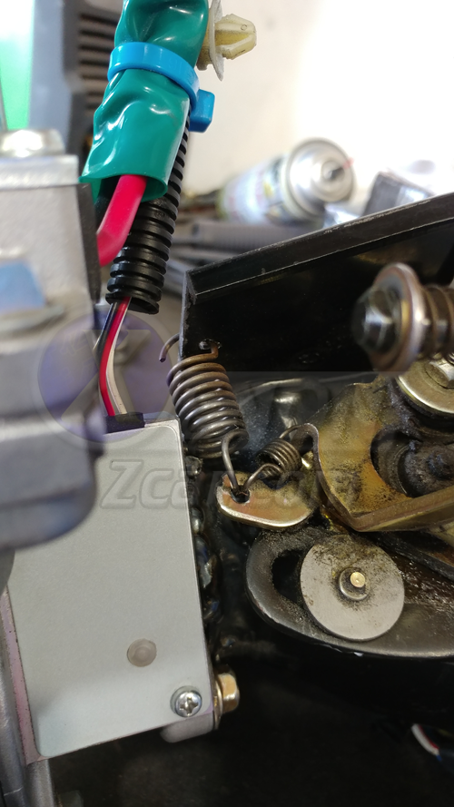
The clutch pedal return spring will come close to the motor, but it should (barely) clear. My motor ended up at approximately a 40 degree angle to the flat side of the column mount.
Your brake switches may not clear with the motor mounted upwards. I was able to mount the upper one, but not the lower one. This wasn’t a huge concern for me (no cruise control & manual transmission), but alternative measures may be needed if the motor is mounted up.
Mounting & Welding the Motor
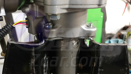
With the stub we prepared earlier inserted into the motor input shaft and universal joint (to aid alignment of the motor to the universal joint), I tacked the motor tube to the column bracket and did another test fit. Make sure everything still fits before fully welding. Weld the tube to the column bracket as straight as possible. I also clearanced the bracket to allow the top two bolts to be inserted from the other side. Drill the threads out of the top two motor mounting holes to use nuts and bolts.

Now, bolt the motor to the column and manipulate it as needed.
Connecting the Motor to the Universal Joint
With the motor affixed, connect it to the front universal joint. You can weld the stub to the input shaft, or make an adapter coupler (recommended to reduce heat to the motor). Cut down the Versa column shaft to match the length of the stub. Insert the stub into the motor shaft and spline sleeve, then tack them together. Fully weld the part off the motor to avoid heat damage. Check for smooth rotation and no binding.
Final Assembly & Bracing
With the steering column assembled, brace the motor tube for extra support. A conduit clamp works, or any sturdy support. The motor is heavy, so ensure strength. This should be your final assembly.
With the column bracket shortened, drill a new hole for the lever return spring (tilt mechanism).
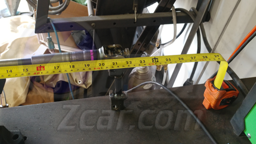
Building the Intermediate Shaft
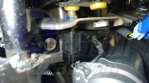
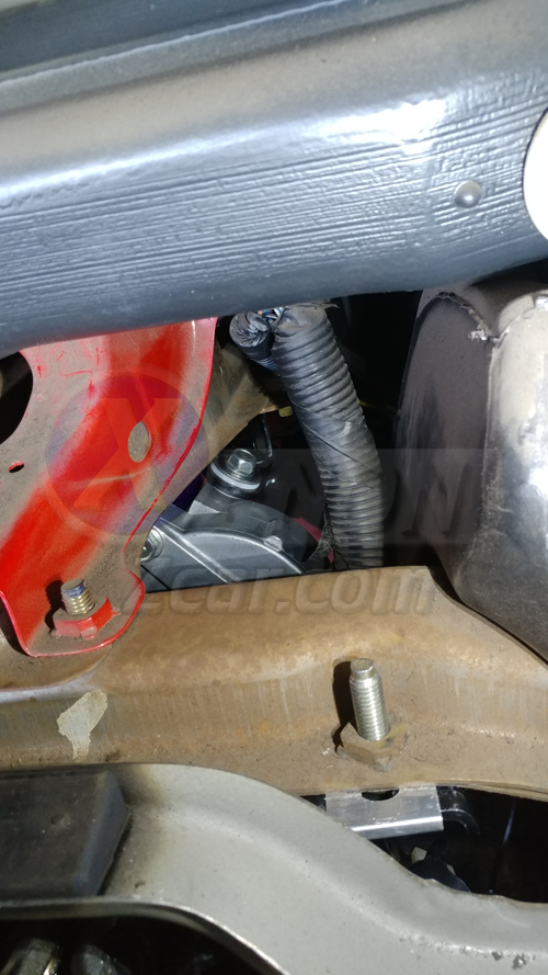
For the new intermediate shaft, merge the stock Versa and Z31 shafts. Cut the end of the Versa shaft (with universal joint and splines) for best results. The Versa has a collapsible shaft—take advantage if you can. At a minimum, the shaft should be 18¼" long (center to center), but can extend. Mine ended up between 19" and 20". Adjust at the spline section in the engine compartment as needed.
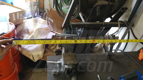

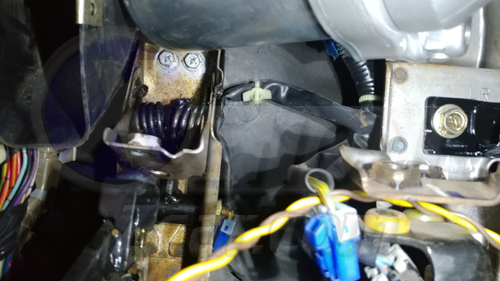
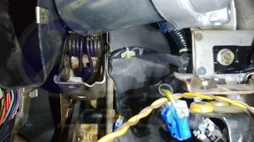
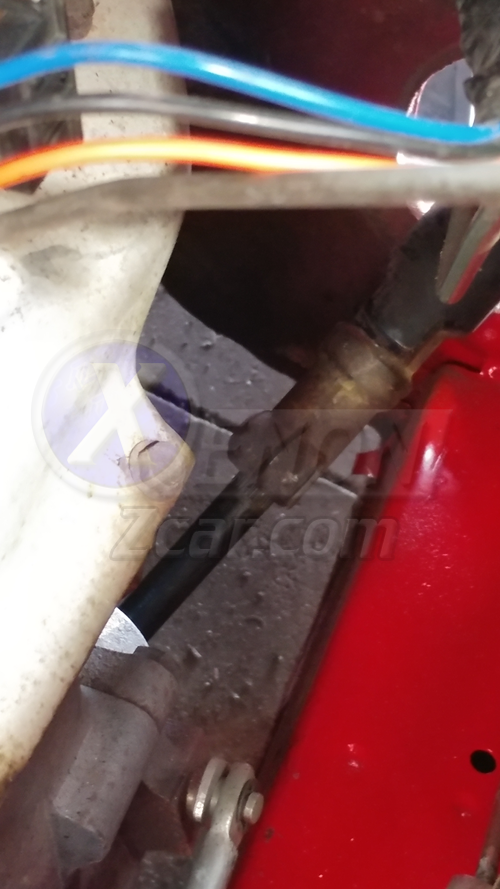 A photo of the spline section referenced
Adapting the Steering Column Length
Now this is an important part. If you cut off the universal joint that has the splines for the motor, you will now see why. The new modified steering column is a couple inches shorter than the stock one, and as such the steering shaft would be at too low of an angle if it were directly attached to the motor.
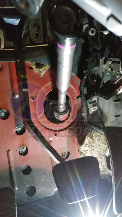
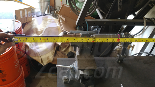
To remedy this, I took a section of the Z31 column I saved from earlier and ground down the ends so it fit into the universal joint ends. The distance between the center of the universal joint to the center of the clamping bolt hole is 5 7/16". Tack the parts together as straight as you can and test fit them to ensure the steering shaft passes through the firewall opening more centrally. I would recommend test fitting the pass through plate as well. Adjust as needed, and weld together. If you didn't cut off the splined universal joint (like me), then you will need to get another steering shaft to get that splined section to fit the motor (A Saturn Vue has the same motor output shaft size). Save yourself the trouble and use the other end.
Fabricating the Rear Motor Mount
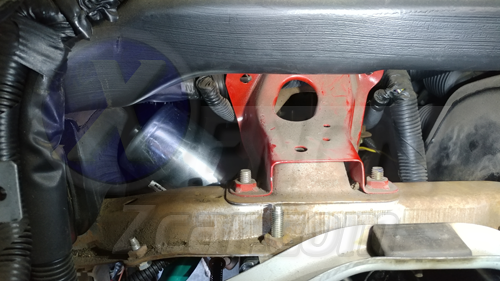
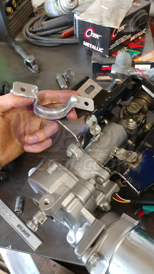
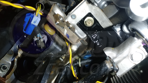
All that is really left is the rear mount for the motor, I left this for last because it was a lot easier to test fit everything without that in the way. I used some of the Versa tilt bracket, and some of the stock rear mount bracket. With the motor mounted upwards, one of the mounting holes is very close by. After some bending, cutting, test fitting, and welding, I ended up with this:
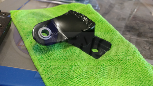
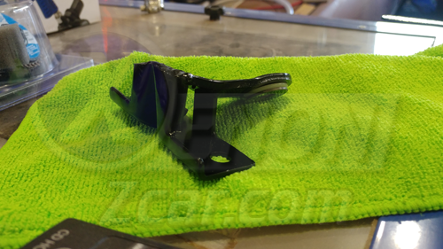
Your bracket may differ depending on how you mount the motor and how you make your bracket. I installed this bracket, and that was the last piece of the mechanical puzzle.
Completing the Mechanical Portion
And with that, the mechanical portion is done. Mount the control computer as you see fit.
Wiring Diagram
Below is a wiring diagram for how the Versa unit is wired. You will see that it is very simple:
 Click for full resolution
And there you have it! This modification should be completable within a weekend if the parts and tools are handy.
Sources Used
- Written by: Kevin Elsner