



Z31 (TPS) Throttle Position Sensor

(TPS) Throttle Position Sensor
The Throttle Position Sensor (TPS) or idle switch is attached to the throttle chamber and actuates in response to accelerator pedal movement.
This switch has both an idle contact and a full throttle contact. The idle contact is used for engine control—closing when the throttle valve is positioned at idle, and opening when it is at any other position.
Warning: do this work at your own risk. We are not responsible for any problems or damage caused by your own work.
Part Numbers
- 22620-V5011 Auto Replaced by 22620-12G11
- 22620-V5001 Manual Replaced by 22620-V5002
Common Problems
- If your car lurches a little while coasting in gear towards a red light, it may be that the TPS is not quite right and the computer is switching from idle to running. This can make your car lurch a little because the fuel is shut off when you are coasting in gear to save gas. The switch is opening and closing, turning the fuel on and off. To replace the switch, simply remove the two screws, unplug it, and replace it with the new one.
- ECU Code #23
- A cracked or brittle TPS connector, or broken wires at the plug. After decades of engine heat the plastic and wire insulation get brittle, causing intermittent idle and shifting problems.
Replacement TPS Wiring Pigtail
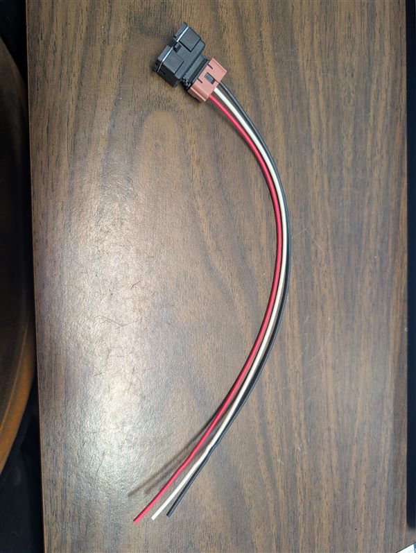
If your TPS plug is cracked, the locking tab is broken, or the wires are brittle at the connector, XenonZcar sells a 3-pin TPS repair pigtail for the 300ZX (Z31 and Z32). It's a new connector with wire leads you splice into your harness, so you don't need to replace the whole harness.
- Fits the 3-pin TPS (idle switch) connector
- Solder and heat shrink each splice, and stagger them so the harness stays slim
- Match the wires one at a time so you don't mix up the pins
Troubleshooting

How to Test the TPS
1. Disconnect the 3-pin connector on the TPS.
2. Test for continuity between the top and middle pin when the throttle is closed.
- Continuity should be present when the throttle is closed.
- The continuity should break as soon as the throttle opens slightly.
If the contact doesn't break until further throttle movement, adjust the TPS by slightly loosening the mounting screws and rotating the sensor until the contacts break when the throttle just begins to open.
 Click image for larger view
TPS Automatic Transmission Potentiometer Pinout
On automatic transmission models, the TPS also includes a potentiometer which sends signals to the Transmission Control Module and Lock-up Control Unit to control shift points and torque converter lockup.
The pinout for this connector is as follows:

| Pin | Color | Connection |
|---|---|---|
| Pin 1 | Blue | Lockup Control Unit Pin 3 |
| Pin 2 | White (shielded) | Pin 18 Lock-up Control Unit |
| Pin 3 | Black | Ground for TPS - Pin 5 Lock-up Control Unit |
Sources Used
- 1984-1988 Nissan 300ZX Factory Service Manual
- Automatic TPS connector Picture by: Michael Littleton On Facebook