


Z31 Crank Angle Sensor
Crank Angle Sensor (CAS)
The crank angle sensor is a basic signal sensor for the entire ECCS. It monitors engine speed and piston position, sending signals to the ECCS control unit to control fuel injection, ignition timing, idle speed, fuel pump operation, and EGR operation.
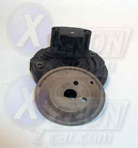
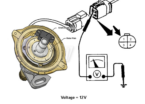
The crank angle sensor contains a rotor plate and a wave form circuit. The rotor plate has 360 slits for the 1° signal (engine speed signal) and six slits for the 120° signal (crank angle signal). Built-in LEDs and photo diodes within the wave forming circuit generate signals as the slits pass between them.
When the signal plate passes through the space between the LED and photo diode, each slit alternately cuts the light. This interruption creates an alternating voltage, which is then converted to an on-off pulse by the wave forming circuit. The signal is sent to the control unit via the green wire with yellow trace, which connects to pin 8 on the ECCS.
*WARNING* - Do this modification at your own risk. We Are not responsable for any issues of your own doing.
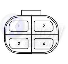
Sensor Pinout
Below you will see the pinout of the Crank Angle Sensor. Click on each pin area for details.
Common Problems
- No Spark
- No Fuel From the Injectors but Fuel at the rail
Troubleshooting
The ECCS of the Z31 will flash trouble codes using two LED lamps on the ECU. A chart of these codes is available on the ECU page.
-
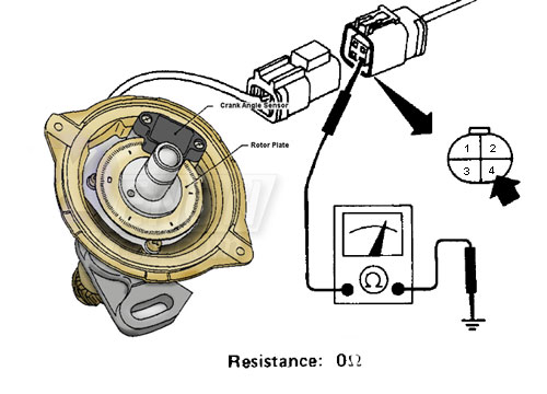
Check ground at Pin 4: Disconnect the 4-pin crank angle sensor connector at the sensor. Measure resistance to ground on Pin 4. It should read 0 Ω. If not, you have a bad ground—repair or replace the harness.
-
Check voltage at Pin 1: With the ignition ON, use a multimeter to check for battery voltage on Pin 1 of the connector.
-
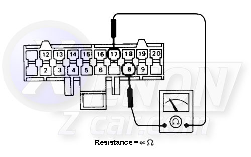
Check harness continuity: If steps 1 and 2 are good, disconnect the 20-pin connector at the ECCS unit and check resistance between Pins 8 and 17. This ensures no broken insulation or open circuit in the harness.
-
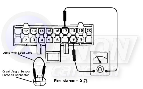
Final continuity test: Add a jumper wire between Pins 2 and 3 of the Crank Angle Sensor plug. Then, test for continuity (should be 0 Ω) between Pins 8 and 17 on the 20-pin connector at the ECCS unit.
If any of these tests fail, repair the harness or replace the faulty sensor as needed.
Replacement
The video below will guide you through the steps for replacing the Crank Angle Sensor. You can even use a newer 1990s S13 240SX Crank Angle Sensor unit.
Interchange
Vehicles Using the Same Crank Angle Sensor (CAS) as the Z31
| Make | Model | Years |
|---|---|---|
| INFINITI | G20 | (1991 - 1994) |
| INFINITI | M30 | (1990 - 1992) |
| ISUZU | TROOPER | (1988 - 1991) |
| MERCURY | VILLAGER | (1993 - 1998) |
| NISSAN | 200SX | (1984 - 1987) |
| NISSAN | 240SX | (1989 - 1990) |
| NISSAN | 280ZX | (1981 - 1983) |
| NISSAN | 300ZX | (1984 - 1989) |
| NISSAN | 720 PICKUP | 1986 |
| NISSAN | AXXESS | (1990 - 1995) |
| NISSAN | D21 PICKUP | (1986 - 1994) |
| NISSAN | MAXIMA | (1985 - 1994) |
| NISSAN | MULTI | (1986 - 1988) |
| NISSAN | NX | (1992 - 1993) |
| NISSAN | PATHFINDER | (1987 - 1995) |
| NISSAN | PICKUP | 1995 |
| NISSAN | PULSAR NX | (1983 - 1986) |
| NISSAN | QUEST | (1993 - 1998) |
| NISSAN | SENTRA | (1984 - 1994) |
| NISSAN | STANZA | (1986 - 1992) |
| NISSAN | VAN | (1987 - 1988) |
| SUBARU | DL | (1987 - 1989) |
| SUBARU | GL | (1987 - 1989) |
| SUBARU | GL-10 | (1987 - 1989) |
| SUBARU | LOYALE | (1990 - 1994) |
| SUBARU | RX | (1987 - 1989) |
| SUBARU | STANDARD | 1987 |
| SUBARU | XT | (1987 - 1991) |