



Installing JDM Fender Mirrors on Your LHD S30
Japanese-market Fairlady Zs came with mirrors on the front fenders instead of on the doors, and they are one of the most popular JDM touches for a U.S. 240Z, 260Z or 280Z. The install is simple: two holes in each fender. The hard part is deciding exactly where those holes go, because the placement diagram that circulates online was measured from a right-hand-drive car and has to be flipped for a left-hand-drive car.
*WARNING* - Drilling your fenders can't be undone. Measure twice, mock it up, and do this at your own risk.
Parts
- Genuine Nissan NOS mirror set for 1969–78: sold by JDM Car Parts (their part 30-J4135). They also sell a paper drilling template for each side (30-J4284-T).
- Reproduction mirror set for 1970–78: sold in left and right pairs by The Z Store.
- Wide masking tape, a tape measure, a center punch, a 13/64" (5mm) drill bit, and a 3/4" (19mm) hole saw or step drill.
- Touch-up paint or primer for the bare metal edges of the holes.
Placement
Every measurement is taken from two edges on the fender to the edge of the mirror base, not to either hole:
- Out: from the inner edge of the fender (the hood gap) outward to the inner edge of the mirror base.
- Back: from the rear edge of the headlight bucket back to the mirror base.
Option 1: Offset (factory diagram, flipped for LHD)
The common diagram was measured from Alan Thomas's right-hand-drive Fairlady 240ZG. It puts the driver's mirror closer in and further forward than the passenger mirror, so the driver can see down both sides of the car. For a left-hand-drive car, swap the sides:
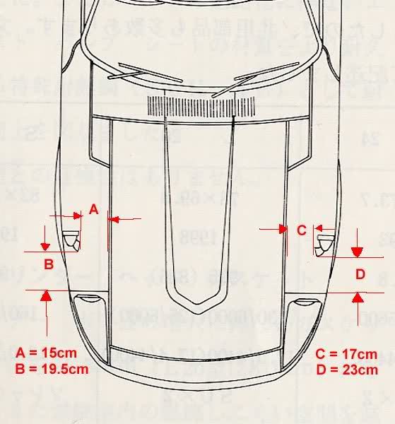
| LHD car | Out from inner edge of fender | Back from rear edge of headlight bucket |
|---|---|---|
| Driver (left), diagram A and B | 5.91 in, about 5 15/16" (15 cm) | 7.68 in, about 7 11/16" (19.5 cm) |
| Passenger (right), diagram C and D | 6.69 in, about 6 11/16" (17 cm) | 9.06 in, about 9 1/16" (23 cm) |
On a right-hand-drive car, use the diagram as drawn: the driver (right) side gets 5.91 in (15 cm) out and 7.68 in (19.5 cm) back, and the passenger (left) side gets 6.69 in (17 cm) out and 9.06 in (23 cm) back.
Option 2: Even (both sides the same)
JDM Car Parts points out that genuine Nissan replacement fenders sold in Japan were drilled in the same place on both sides, even though some 1970s service literature shows the offset layout. The Z Store gives this even position for both sides:
| Both sides | Out from inner edge of fender | Back from rear edge of headlight bucket |
|---|---|---|
| Driver and passenger | 7 in (17.8 cm) | 10.5 in (26.7 cm) |
Either layout is correct for a Fairlady Z. Offset gives the driver a better view; even looks symmetrical from the front.
The Holes
| Hole | Size | Purpose |
|---|---|---|
| Main hole | 3/4" (19mm) | Mirror stud and spring base |
| Pin hole | 13/64" (5mm) | Anti-swing pin that keeps the mirror from turning |
| Spacing | About 1" (25mm) center to center | Check it against your mirror base before drilling |
Step by Step
- Pick your layout (offset or even) and write the numbers for each side on a piece of tape so you don't mix them up.
- Tape the fender. Run wide masking tape over the area so you can mark on it and protect the paint from the drill.
- Measure out first, from the inner edge of the fender, then measure back from the rear edge of the headlight bucket. Mark the edge of the mirror base, then use the base itself to mark where the two holes fall.
- Mock it up. Have a helper hold the mirror on the marks while you sit in the driver's seat and check the view. Small changes are fine; this is the last chance to make them.
- Look underneath. The spring base hangs below the fender. Check that nothing is in the way under each mark before drilling.
- Drill. Center punch, drill the 13/64" (5mm) pin hole, then drill a small pilot and open the main hole to 3/4" (19mm) with a hole saw or step drill. Go slowly so the bit doesn't walk.
- Seal the metal. Remove the tape, deburr the holes and paint or prime the bare edges so they don't rust.
- Install the mirror from the top with the pin in the small hole, and fit the nut from underneath. Repeat on the other side with its own measurements.
Adjusting
- Don't overtighten the bottom nut. It sets the spring tension, and the mirror should still fold if something bumps it.
- Aim the glass by loosening the Phillips screw on the back of the mirror head, then tighten it again so it can't vibrate loose and fall off while driving.
Sources Used
- The Z Store: Reproduction Fairlady Z Fender Mirror Set, for the LHD, RHD and even measurements and hole sizes
- JDM Car Parts: Genuine Nissan NOS Fender Mirror Set, for symmetrical factory fenders, hole sizes and adjustment
- Classic Zcar Club: Fender Mirror Placement, for the origin of the RHD diagram and measuring to the base
- HybridZ: Fender Mirror Template and HybridZ: Fender Mirror Installation on a 71 240Z, for flipping the diagram for LHD and mocking up first
- AusZcar fender mirror placement diagram (RHD), measured from Alan Thomas's Fairlady 240ZG