



S30 Sensor Guide
A listing of the sensors and switches that make the S30 run and that feed its gauges, with locations and test values from the factory service manuals. The carbureted 240Z and 260Z only have the gauge senders. The 1975–78 280Z adds the Bosch L-Jetronic fuel injection sensors, which are where most driveability problems start.
*WARNING* - Do this diagnosis at your own risk. We are not responsible for any issues of your own doing. Disconnect the battery ground cable before unplugging any fuel injection connector.
Sensor List
| Sensor | Years | Location | What it does |
|---|---|---|---|
| Air flow meter | 1975–78 | Between the air cleaner and the throttle chamber | Measures intake air with a spring-loaded flap; the main input to the control unit. Also holds the fuel pump contacts |
| Air temperature sensor | 1975–78 | Built into the air flow meter | Adjusts the mixture for intake air temperature |
| Water temperature sensor | 1975–78 | Thermostat housing | Adds fuel while the engine warms up |
| Thermotime switch | 1975–78 | Thermostat housing | Turns on the cold start valve when cranking a cold engine |
| Throttle valve switch | 1975–78 | On the throttle chamber | Idle and full throttle contacts |
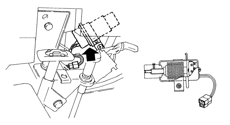
| Altitude switch | 1977–78, California only | Stay at the left side of the instrument panel | Leans the mixture 6% at high altitude |
| Ignition coil signal and starting switch | 1975–78 | Coil negative terminal; ignition switch | Engine speed for injection timing, and the cranking signal |
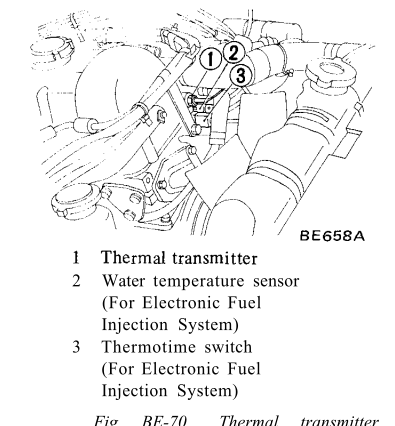
| Thermal transmitter | All years | Thermostat housing area (see figure) | Drives the water temperature gauge |
| Oil pressure gauge unit | All years | Cylinder block beside the oil filter | Drives the oil pressure gauge |
| Fuel tank gauge unit | All years | In the fuel tank | Drives the fuel gauge and low fuel warning light |
Air Flow Meter (1975–78)
The air flow meter is the heart of the L-Jetronic system (the "L" is for Luft, German for air). A flap in the air passage swings open against a coil spring as air flows in, and a potentiometer on the flap shaft sends a voltage to the control unit. A damper chamber keeps the flap from fluttering, and a bypass port, set at the factory, meters the idle air. The manual says not to adjust the bypass in the field.
The fuel pump contacts are also in the air flow meter. They close when the flap opens about 8°, so if the engine stalls the flap closes and the fuel pump stops, even with the key on. While cranking, the pump runs no matter what the contacts do.
Testing (battery disconnected, meter unplugged)
| Terminals | Check | Spec |
|---|---|---|
| 8 – 6 | Resistance | About 180 Ω |
| 9 – 8 | Resistance | About 100 Ω |
| 8 (+) – 7 | Voltage, with 12V DC applied to 9 (+) and 6 (−), while slowly opening the flap by hand | Voltage drops smoothly as the flap opens. A sudden jump means a worn potentiometer |
| 36 – 39 | Fuel pump contacts | Continuity with the flap open about 8°; none with the flap closed |
| Body – 6, 7, 8, 9 | Insulation | No continuity |
| Flap | Open fully by hand | Moves smoothly without binding |
If any check fails, the manual calls for replacing the air flow meter as an assembly. The air temperature sensor is part of it.
Air and Water Temperature Sensors (1975–78)
Both are thermistors: their resistance drops as they warm up. The air temperature sensor is built into the air flow meter and is tested at terminals 27 and 6 of the air flow meter connector. The water temperature sensor screws into the thermostat housing and is tested across its two terminals. A bad water temperature sensor is a classic cause of hard hot starts and rich running, because the control unit thinks the engine is still cold.
The manual gives the same resistance chart for both sensors:
| Temperature | Resistance |
|---|---|
| −30°C (−22°F) | 20.3 to 33.0 kΩ |
| −10°C (14°F) | 7.6 to 10.8 kΩ |
| 10°C (50°F) | 3.25 to 4.15 kΩ |
| 20°C (68°F) | 2.25 to 2.75 kΩ |
| 50°C (122°F) | 0.74 to 0.94 kΩ |
| 80°C (176°F) | 0.29 to 0.36 kΩ |
- On the car: measure cold, using a rod thermometer in the radiator for the reference temperature, then again fully warmed up.
- Off the car: dip the water sensor in 20°C (68°F) water, then 80°C (176°F) water.
- Insulation: no continuity between either terminal and the engine block (water sensor) or between terminal 27 and the air flow meter body (air sensor).
The 1975 manual misprints two temperatures in the water sensor section: −10°C is listed as −18°F and 80°C as 114°F. The correct conversions are shown above.
Thermotime Switch (1975–78)
The thermotime switch sits in the thermostat housing and is wired to the cold start valve. Its bimetal contacts are closed when the coolant is below 14 to 22°C (57 to 71°F), so the cold start valve sprays extra fuel while cranking a cold engine. A small heater warms the bimetal whenever the key is in START, so repeated cranking opens the switch and keeps the engine from flooding.
Static check (battery disconnected, switch unplugged)
| Terminals | Coolant temperature | Spec |
|---|---|---|
| 46 – switch body | Below 14°C (57°F) | 0 Ω |
| 46 – switch body | 14 to 22°C (57 to 71°F) | 0 Ω or infinite |
| 46 – switch body | Above 22°C (71°F) | Infinite |
| 45 – switch body | Any | 70 to 86 Ω (the heater) |
Dynamic check (switch removed)
Put the tip in 10°C (50°F) water. Once it settles, terminals 45 and 46 should read about 78 Ω. Warm the water about 1°C (1.8°F) per second to above 25°C (77°F); the reading should go from about 78 Ω to infinite.
Cold start valve
Remove the valve with its fuel hose still attached, put the nozzle in a clear container (at least 20 cc), and disconnect the S wire at the starter. With the key in START it should not spray when the coolant is above 22°C (71°F). Jumper it to the battery and it should spray. A cold start valve that leaks or sprays when warm causes flooding and hard hot starts.
Throttle Valve Switch (1975–78)
The throttle valve switch is a switch, not a variable sensor like later throttle position sensors. It sits on the throttle chamber and has two sets of contacts. The idle contacts are closed only at idle and tell the control unit to enrich at idle and to cut fuel on deceleration. The full throttle contacts close at about 30° of throttle and up and add fuel at full load.
| Terminals | Check | Spec |
|---|---|---|
| 2 – 18 | Idle contacts | Continuity at idle; open once the throttle is about 7° open |
| 3 – 18 | Full throttle contacts | Lowest reading at about 30° open and beyond; higher at all other positions |
| Body – 2, 3, 18 | Insulation | Infinite |
Altitude Switch (1977–78 California)
California cars from 1977 added an altitude switch on the stay at the left side of the instrument panel, inside the car. It is a bellows and a microswitch. When air pressure drops below about 660 mmHg (26 inHg), roughly 1,120 m (3,675 ft) above sea level, the switch turns on and the control unit leans the mixture by 6%.
| Altitude | Air pressure | Switch | Mixture |
|---|---|---|---|
| Below about 1,120 m (3,675 ft) | 660 mmHg (26 inHg) or above | OFF | Standard |
| Above about 1,120 m (3,675 ft) | 660 mmHg (26 inHg) or below | ON | 6% leaner |
Other Fuel Injection Parts (1975–78)
These aren't sensors, but they're tested along with them:
| Part | Location | Test |
|---|---|---|
| EFI relay | Driver's side dash panel | Two relays in one case: the main relay powers the system and the fuel pump relay runs the pump and air regulator. 12V across the coil should click the contacts closed. The manual suggests a fuse in the test lead |
| Dropping resistor | Near the washer tank | About 6 Ω per cylinder: 43/1 to terminals 37, 38, 40 and 41 (cylinders 1 to 4), and 43/2 to terminals 55 and 56 (cylinders 5 and 6) |
| Injectors | Intake manifold runners | Continuity across the two terminals. At idle, each should click when you touch a screwdriver to it |
| Air regulator | Throttle chamber bypass | Pinching its hose on a cold engine should drop the idle. It should have continuity across its heater and close within a few minutes of running |
| Fuel pressure | At the cold start valve hose | About 2.55 kg/cm² (36.3 psi) above manifold pressure. The pump relief valve opens at 3 to 4.5 kg/cm² (43 to 64 psi) |
Gauge Senders (All Years)
The temperature, oil and fuel gauges are bimetal gauges fed by a gauge voltage regulator. If two gauges go wrong at the same time, suspect the voltage regulator before the senders. Use conductive sealer on the threads of a new temperature or oil sender; they ground through the threads.
| Sender | Location | Quick test (1975 manual) |
|---|---|---|
| Thermal transmitter (water temperature) | Thermostat housing area, next to the EFI water temperature sensor on the 280Z | Put a 116 Ω resistor between the yellow/white wire and ground: the gauge should read about 50°C (122°F). Grounding the wire should swing the gauge |
| Oil pressure gauge unit | Cylinder block beside the oil filter | A variable resistor on a diaphragm. If the gauge reads zero and the gauge is good, replace the unit |
| Fuel tank gauge unit | In the fuel tank | Put a 32 Ω resistor between the yellow wire and ground: the gauge should read half. Grounding the wire should swing the gauge |
The 1975 280Z still used an ammeter with a shunt on the relay bracket in the right side of the engine compartment. The 1976 manual replaces it with a voltmeter that has a built-in charge warning light. See Model Year Differences.
Sources Used
- 1975 Datsun 280Z Factory Service Manual, section EF (Engine Fuel), pages EF-3 to EF-16 and EF-51 to EF-58, and section BE (Body Electrical), pages BE-41 to BE-45
- 1976 Datsun 280Z Factory Service Manual, sections EF and BE (same test values as 1975; voltmeter)
- 1977 Datsun 280Z Factory Service Manual, section EF, page EF-15 (altitude switch)
- 1978 Datsun 280Z Factory Service Manual, section EF, page EF-3 (sensor list)